Home / Door Hardware
Installation Guide for VEVOR Entry Door Knobs
Step-by-step installation guide for VEVOR entry door knobs (models 209BK-MB-6PK, 587ET-SS-1PK). Includes drilling requirements, latch adjustment, and maintenance instructions.
Quick answers from the manual
Quick answer
- This manual provides installation instructions for VEVOR entry door knobs, including drilling requirements, latch adjustment, and maintenance. p. 1, 3, 4, 5
Key actions
- Drill a 54mm hole for the lock body and a 25mm hole for the latch. p. 3
- Adjust the latch backset by pushing the turning wheel. p. 5
Problems and fixes
Key is not smoothly inserted and removed
Add graphite powder (pencil powder) in the keyhole to lubricate.
p. 5Show 3 more answers Show less
Maintenance and reset
- Clean with a dry cloth; do not use chemicals. Lubricate keyhole with graphite powder periodically. p. 5
Technical specifications
| Parameter | Value | Meaning | Pages |
|---|---|---|---|
| Door Thickness | 1-3/8" to 1-3/4" | Compatible door thickness range. | p. 6 |
| Backset | 2-3/8" to 2-3/4" | Adjustable latch distance. | p. 6 |
Where to find it in the PDF
- Installation Tools and Drilling p. 3
- Installation Steps p. 4
- Adjustable Latch and Maintenance p. 5
Table of contents
Manual images
Click an image to enlargeQuick guide from the manual
This manual provides instructions for installing VEVOR entry door knobs. Key requirements include a door thickness of 1-3/8" to 1-3/4" and an adjustable backset of 2-3/8" (60mm) or 2-3/4" (70mm). Always ensure the keyhole is in the downward position during installation.
Installation tools
Required for replacement: Phillips screwdriver.
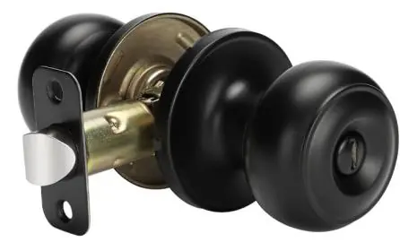
Required for new installation:
- Measuring tape
- 1" (25mm) hole boring bit
- 2-1/8" (54mm) hole boring saw
- Additional tools (if needed): chisel, hammer, pencil, safety glasses
Drilling holes
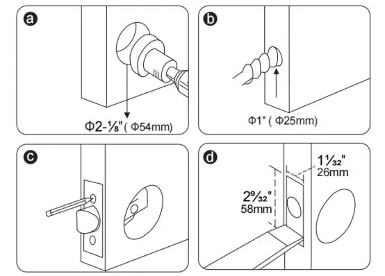
- Fold the template at the dotted line and tape it to the interior side of the door at 34 to 48 inches in height.
- Measure the door thickness and mark the middle point.
- Mark the hole center for the backset (60mm or 70mm). Ensure both dots are at the same height.
- Drill a 54mm (2-1/8") hole for the lock body.
- Drill a 25mm (1") hole for the latch.
- Insert the latch to mark the faceplate outline, then chisel a 3mm deep hole for the faceplate.
Installation instructions
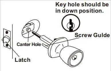
- Install the latch: Insert the deadbolt latch in the "up" position into the door hole and secure with screws.
- Install striking plate: Place against the jamb as illustrated to prevent forcing when the door is closed.
- Install outside knob unit: Engage the screw guides, locking bar, and spindle into the latch. Ensure the keyhole is in the down position.
- Install inside knob unit: Engage the screw guides, locking bar, and spindle into the inside unit, then insert and tighten screws securely.
Adjustable latch
The latch can be adjusted for different backsets:
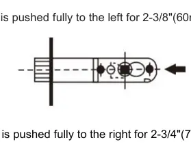
- 2-3/8" (60mm) backset: Push the turning wheel fully to the left.
- 2-3/4" (70mm) backset: Push the turning wheel fully to the right.
Note: During adjustment, keep the two teeth of the turning wheel facing forward.
Maintenance
- Do not strike the lock with force to avoid damage.
- Clean with a dry cloth only. Do not use chemicals or dishwashing liquid, as this will destroy the protective film and cause fading.
- If the key does not insert or remove smoothly, lubricate the keyhole with graphite powder (pencil powder) once every six months or once a year.
Product parameters
Compatible with doors 1-3/8" to 1-3/4" thick. Models 209BK-MB-6PK and 587ET-SS-1PK feature adjustable latches (2-3/8" to 2-3/4") and are constructed from 201 stainless steel, zinc alloy, and zinc-coated copper.
Manufacturer information
VEVOR
Practical help
Common problems
Key does not insert or turn smoothly
Apply graphite powder (pencil powder) into the keyhole to lubricate.
Latch does not fit the door backset
Adjust the turning wheel on the latch to switch between 2-3/8" (60mm) and 2-3/4" (70mm).
Before use
- Ensure you have a Phillips screwdriver, measuring tape, 1" hole boring bit, and 2-1/8" hole boring saw.
- Verify door thickness is between 1-3/8" and 1-3/4".
- Check if you need a chisel, hammer, or pencil for marking.
- Wear safety glasses during installation.
Show more Show less
Specs in practice
- Door Thickness
- Compatible with doors 1-3/8" to 1-3/4" thick.
Images and diagrams
- The template should be folded at the dotted line and taped to the door at 34-48 inch height.
- The turning wheel on the latch must be pushed to the left for 60mm backset or right for 70mm backset.
Model compatibility
- Compatible with door thickness 1-3/8" to 1-3/4".
- Supports backsets of 2-3/8" (60mm) or 2-3/4" (70mm).

Manual page author
Emily Carter
User documentation editor