Automotive / Motorcycle Accessories
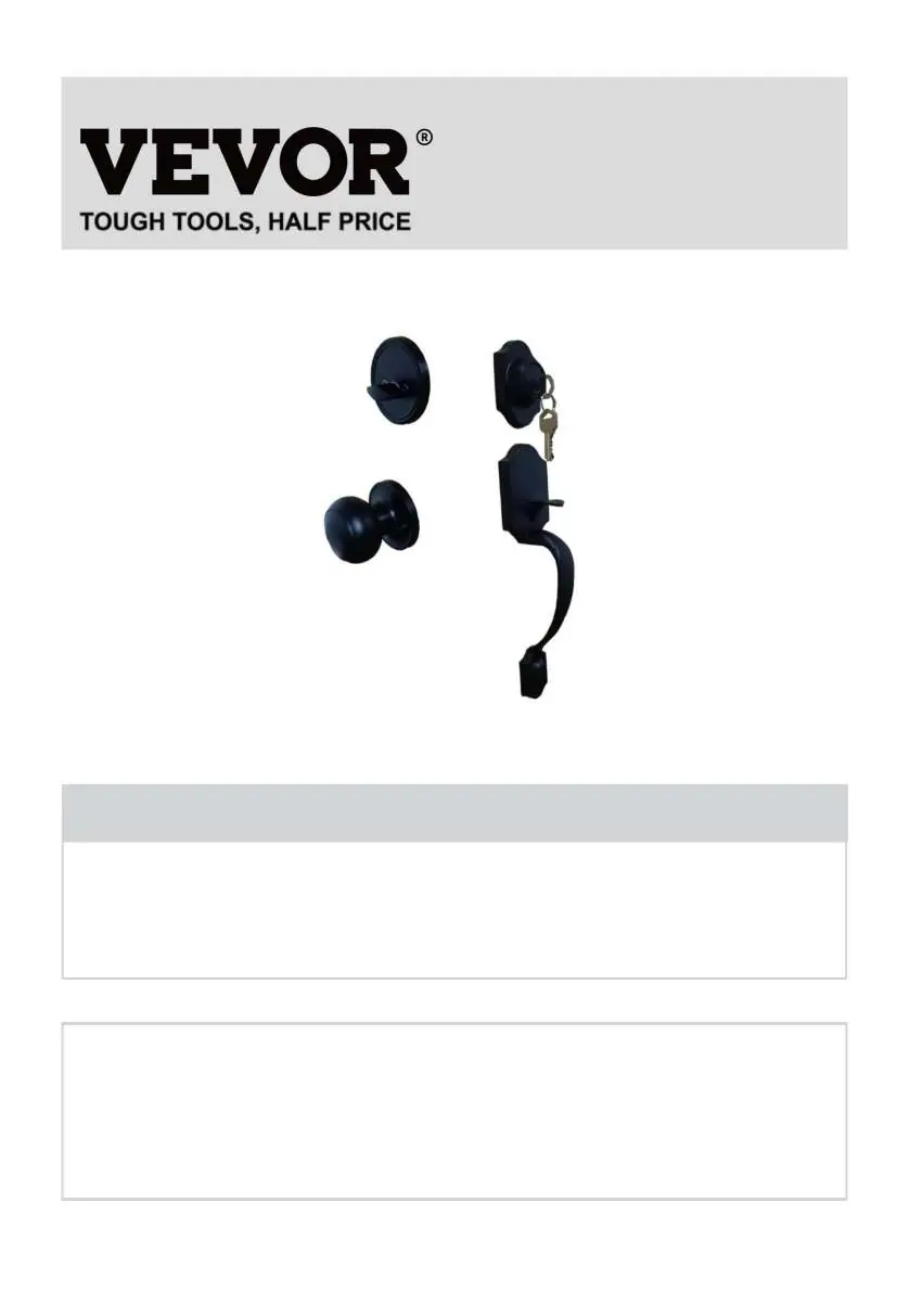
User Manual for VEVOR Knob Handlesets 19985-SN, 20185-AC, 20185-10B
Comprehensive installation and maintenance guide for VEVOR Knob Handlesets (models 19985-SN, 20185-AC, 20185-10B). Includes component diagrams, door preparation, and step-by-step assembly instructions.
Quick answers from the manual
Quick answer
- This manual provides installation and maintenance instructions for VEVOR Knob Handlesets (models 19985-SN, 20185-AC, 20185-10B). p. 1
Key actions
- Install the latch by adjusting it to the 60mm or 70mm backset. p. 4
- Install the exterior handle mechanism. p. 5
First start
- Mark the door and bore the required 54mm and 25mm holes. p. 4
Problems and fixes
Key insertion is not smooth
Add graphite powder (pencil powder) to the keyhole.
p. 6Maintenance and reset
- Lubricate the keyhole with graphite powder periodically. p. 6
Technical specifications
| Parameter | Value | Meaning | Pages |
|---|---|---|---|
| Door Thickness | 1-3/8"~1-3/4" | Compatible door thickness range | p. 2 |
Where to find it in the PDF
- Structure Diagram p. 3
- Installation p. 4, 5
Table of contents
Manual images
Click an image to enlargeQuick guide from the manual
This document provides installation and maintenance instructions for VEVOR Knob Handlesets (models 19985-SN, 20185-AC, 20185-10B). Key steps include preparing the door, installing the latch, and mounting the handle mechanism. Regular maintenance, such as lubrication with graphite powder, is recommended to ensure smooth operation.
Safety instructions
- Choking Hazard: This product contains small parts. Keep them away from children.
- Power Tool Safety: Always wear safety glasses or eye shields before assembly and when using power tools.
- Operation: Keep hands, face, hair, and loose clothing away from spindles and cutting tools. Always disconnect power sources before adjusting power tools.
Technical parameters
- Applicable Door Thickness: 1-3/8" to 1-3/4"
- Latch Length: 2-3/8" and 2-3/4"
- Pitch-row (Door Handle): 7-11/16" to 8-13/16"
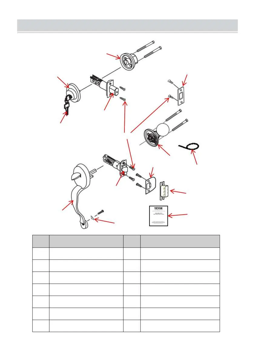
Components list
The set includes the following components:
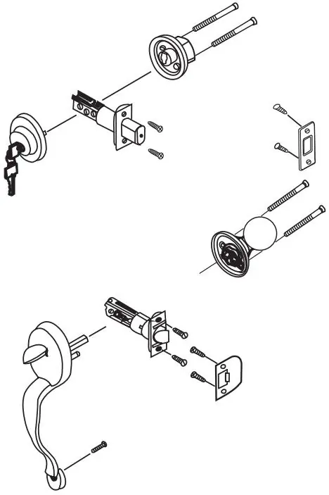
- Front Handle
- Lower Latch
- Cylinder
- Deadbolt Rose
- Strike Plate
- Back Knob
- Strike Box
- Screws
- Pin
- Door Key
- Washer
Installation
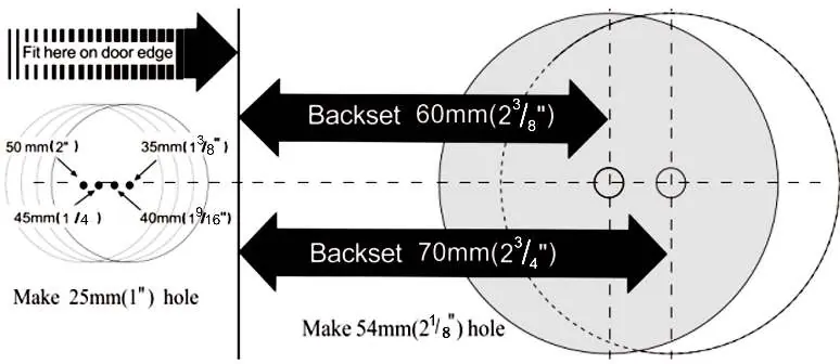


1. Mark door and bore holes
Fold the template over the edge of the door and mark the 60mm or 70mm hole positions. Bore the 54mm and 25mm holes through the door. Cut out a 58x26x3mm base.
2. Install the latch
Adjust the latch to 60mm or 70mm based on the lock hole position. Note: The cam is pushed fully to the right for a 70mm backset. Keep two teeth of the cam facing forward during adjustment.
3. Install exterior handle mechanism
Place the front handle with stems and square spindle into the latch. Press tightly against the door face.
4. Install interior knobs
Install the interior knob and tighten the screws. Insert the screw through the washer and into the bottom hole, then tighten firmly.
5. Install the strikes
Install the strike plate and strike box on the door jamb. The locking bar is pressed down when the door is closed.
Maintenance
- Do not strike the latch or door frame with force.
- Clean with a dry cloth only. Do not use chemical cleaners (e.g., dishwashing liquid) as they damage the protective film.
- Periodically (every 6 months to 1 year) or when the key insertion feels stiff, add graphite powder (pencil powder) to the keyhole for lubrication.
Manufacturer information
VEVOR
Practical help
Common problems
Key insertion is not smooth
Lubricate the keyhole with graphite powder (pencil powder).
Dirt on the handle surface
Use a dry cloth to remove dirt. Do not use chemical cleaners as they will destroy the protective film and cause fading.
Before use
- Verify door thickness is between 1-3/8" and 1-3/4".
- Ensure you have all components listed in the structure diagram.
- Wear safety glasses before assembly.
- Disconnect power tools before adjusting.
- Check the latch backset (60mm or 70mm) before installation.
Specs in practice
- Door Thickness
- Compatible with doors 1-3/8" to 1-3/4" thick.
- Latch Length
- Adjustable to 2-3/8" or 2-3/4".
Images and diagrams
- The structure diagram identifies all parts by number for easy assembly.
- The installation diagram shows the required hole sizes (54mm and 25mm) and backset measurements.
Model compatibility
- Compatible with door thicknesses of 1-3/8" to 1-3/4".

Manual page author
Emily Carter
User documentation editor
Prepares concise manual descriptions and highlights the most useful setup, operation, and maintenance information for readers.