Lighting / Outdoor Landscape
Vista 1182SE Architectural Series Semi Recessed Ingrade Installation Instructions
Installation guide for the Vista 1182SE Architectural Series Semi Recessed Ingrade light. Includes step-by-step instructions for conduit setup, wiring, drainage requirements, and sealing procedures.
Table of contents
Important Installation Notes
Before beginning the installation of the Vista 1182SE, please review the following requirements to ensure safety and product longevity:
- Power: Always turn off the main power at the circuit breaker before installation. Do not install the fixture while the system is energized.
- Compliance: The luminaire must be installed and grounded in accordance with the National Electrical Code (NEC) and local codes.
- Environment: This fixture is wet location listed and suitable for semi-recessed mounting into an outer housing sleeve.
- Wiring: Suitable for through wiring with a maximum of (4) No. 12 AWG conductors (plus ground) rated for 90°C.
- Sealing: All conduit entries must be sealed from moisture using appropriate sealing material.
Installation Steps
- Install the conduit in the bottom hub of the Rough-In Section (RIS) so that it extends beyond the length of the Outer Sleeve.
- Place the Rough-In Section (RIS) into the Outer Sleeve and secure it with screws. The top of the RIS should be approximately 5/16” below the top of the Outer Sleeve.
- Connect conduit sweeps to the conduit lengths installed in the RIS to align with horizontal conduit runs as needed.
- Excavate a hole to the desired depth, ensuring it is approximately 6”–10” larger in diameter than the Outer Sleeve.
- Place the Sleeve/RIS/conduit assembly into the hole. Backfill around and below the Outer Sleeve to anchor it.
- Provide a minimum of 6” of pea gravel at the bottom of the housing tube to ensure proper drainage.
- Connect the conduit from the assembly to the supply conduit, ensuring it is trenched and buried in compliance with NEC standards.
- The RIS functions as the Splicing Compartment. Pull electrical supply conductors into the RIS, taking care not to damage the outer flange.
- Connect the supply conductors from the Lamp Module into the RIS Splicing Compartment.
- Use the supplied duct seal compound to plug the conduit entries fully. Pour re-enterable potting compound into the Splicing Compartment cavity after connections are made to ensure a watertight seal. Do not overfill; use only enough to cover the splicing.
- Position the Lamp Module into the RIS and secure it using the two supplied screws. Ensure the perimeter red sealing gasket is in place and undamaged.
Maintenance
To maintain proper operation and prevent overheating, the lens must be kept clean and free of dirt, dust, leaves, trash, and mineral deposits from water. A regular maintenance schedule is recommended.
Safety Warnings
Debris Clearance: Keep the top and interior of in-grade fixtures clear of debris. Excessive heat can create a fire hazard or damage components. Never install these fixtures in mulch, wood chips, or other potentially ignitable materials, as this will void the warranty and may result in serious injury or property damage.
Practical help
Common problems
Overheating or fire hazard
Keep the top and interior of the fixture clear of debris (mulch, wood chips, leaves). Do not install in ignitable materials.
Moisture ingress
Ensure all conduit entries are plugged with duct seal compound and the Splicing Compartment is sealed with re-enterable potting compound.
Drainage issues
Ensure a minimum of 6 inches of pea gravel is placed at the bottom of the housing tube.
Before use
- Turn off main power at the circuit breaker.
- Verify conduit is installed in the RIS bottom hub.
- Ensure excavation hole is 6-10 inches larger than the Outer Sleeve.
- Check that the perimeter red sealing gasket is present and undamaged.
- Confirm wiring complies with NEC standards.
Specs in practice
- Conduit Capacity
- Max (4) No. 12 AWG conductors (plus ground) rated for 90°C.
- RIS Positioning
- The top of the RIS should be ~5/16” below the top of the Outer Sleeve.
- Excavation Size
- Hole should be 6”-10” larger in diameter than the Outer Sleeve.
Images and diagrams
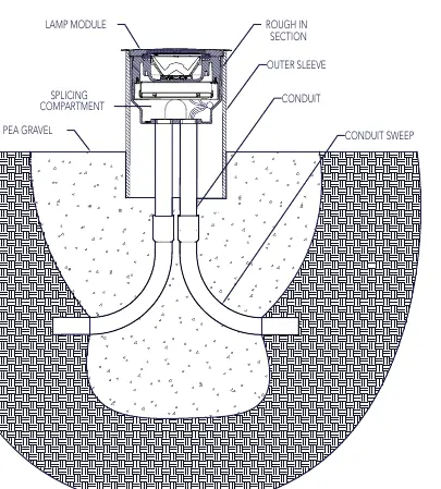
- The diagram illustrates the assembly stack: Lamp Module at the top, followed by the Splicing Compartment, RIS, and Outer Sleeve.
- It highlights the drainage layer (pea gravel) at the bottom and the surrounding earth backfill.
- It shows the conduit and conduit sweep connections entering the bottom of the RIS.
Model compatibility
- Suitable for through wiring.
- Wet location listed.
- Designed for semi-recessed mounting into an outer housing sleeve.

Manual page author
Michael Turner
Technical manual editor
Reviews PDF manuals for structure, safety notes, and practical product details so readers can find the right information quickly.