Lighting / Ceiling Fans
User Manual for Visual Comfort & Co. 14PRR72XXXD Series Ceiling Fan
Comprehensive installation and operation guide for the Visual Comfort & Co. 14PRR72XXXD Series ceiling fan. Includes detailed wiring instructions, remote control pairing, and troubleshooting steps.
Table of contents
Manual images
Click an image to enlargeQuick Guide
This manual provides instructions for the installation and operation of the Visual Comfort & Co. 14PRR72XXXD Series ceiling fan. Before beginning, ensure the power is turned off at the service panel. The fan requires a metal outlet box suitable for fan support (must support at least 35 lbs). The fan is suitable for damp locations, such as covered or enclosed patios or porches.
Safety Information
- Installation must be performed by qualified personnel in accordance with ANSI/NFPA 70.
- Always turn off power at the service panel before installation, servicing, or cleaning.
- Ensure a minimum clearance of 7 feet from the floor to the trailing edge of the blade.
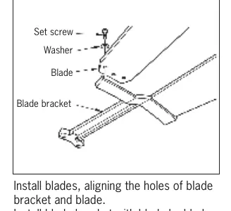
- Do not bend blade holders during installation or cleaning.
- Use only the provided mounting screws with the outlet box.
- Do not use solid-state fan speed controls other than the specified part (DC8).
Installation
Mounting and Downrod: Ensure the outlet box is securely fastened to the house structure. Remove the preassembled keeper pin and cross pin from the downrod. Thread lead wires and safety cable through the downrod. Secure the downrod to the motor housing using the cross pin and keeper pin, then tighten the set screws. Install the ball end of the downrod into the mounting bracket, ensuring the slot on the ball aligns with the tab on the bracket.
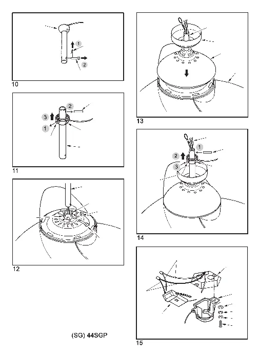
Safety Cable: Required for outdoor applications, installations in Canada, and USA fan/light combinations over 35 lbs. Secure the safety cable to the house structure using the provided 3-inch lag screws, washers, and lock washers.
Wiring
Connect the wires using the provided wire connectors as follows:
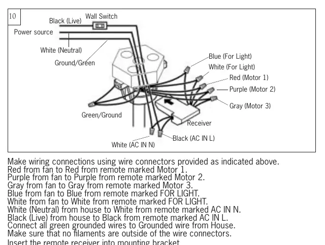
- Red (fan) to Red (remote, Motor 1)
- Purple (fan) to Purple (remote, Motor 2)
- Gray (fan) to Gray (remote, Motor 3)
- Blue (fan) to Blue (remote, FOR LIGHT)
- White (fan) to White (remote, FOR LIGHT)
- White (house, Neutral) to White (remote, AC IN N)
- Black (house, Live) to Black (remote, AC IN L)
- Green (house/fan) to Ground
After wiring, spread the grounded and ungrounded conductors on opposite sides of the outlet box and push splices upward.
Remote Control Operation
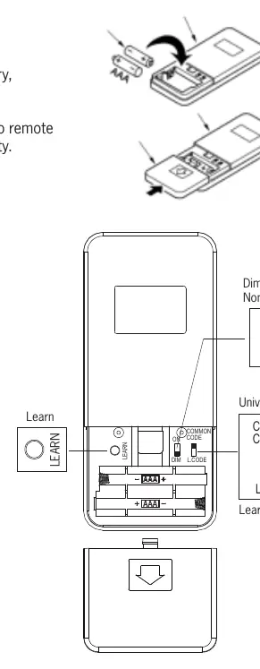
The remote offers two modes: Universal Mode (dip switch at UPPER position) and Learning Mode (dip switch at LOWER position). To pair in Learning Mode, restore power to the fan and press the LEARN button within 60 seconds for at least 3 seconds. The light will twinkle twice to confirm pairing. The remote supports dimming (DIM position) and non-dimming (ON position) settings.
Troubleshooting
- Fan does not start: Check circuit fuses, line wire connections, and remote dip switch settings. Ensure the wall switch is fully engaged.
- Noisy operation: Check that all motor housing screws are snug, blade holder screws are tight, and wire connectors are not rattling. Allow a 24-hour break-in period.
- Wobbling: Ensure the mounting bracket ridge engages the downrod ball notch. Check that all blade holders are tight. If necessary, use the provided balancing kit.
- Light does not work: Check blue wire connections, light kit wiring, and ensure the lightbulb is tight.
Practical help
Common problems
Fan does not start
Check circuit breakers, verify wire connections, ensure the wall switch is fully on, and check remote dip switch settings/battery.
Noisy operation
Tighten motor housing and blade holder screws. Ensure wire connectors are not rattling. Allow 24 hours for the 'break-in' period.
Fan wobbles
Ensure the mounting bracket ridge engages the downrod ball notch. Check that all blade holders are tight. Use the provided balancing kit if needed.
Light does not work
Check blue wire connection, verify light kit wiring, and ensure the bulb is tight in the socket.
Before use
- Turn off power at the service panel.
- Ensure the outlet box is suitable for fan support (must support at least 35 lbs).
- Gather required tools: Electrical Tape, Phillips Screwdriver, Pliers, Safety Glasses, Stepladder, Wire Strippers.
- Verify the ceiling angle is not steeper than 20 degrees if using an angle mount.
- Ensure the safety cable is installed for outdoor use or heavy fan/light combinations.
Specs in practice
- Power Supply
- AC 120V/60Hz only.
- Weight Support
- The outlet box must support at least 35 lbs (15.9 kg).
Images and diagrams
- Wiring Diagram: Shows connections between the house power source, the remote receiver, and the fan motor/light.
- Remote Control: Illustrates the dip switch settings for Universal vs. Learning mode and the location of the LEARN button.
- Downrod Assembly: Details the insertion of the cross pin and keeper pin through the downrod and motor yoke.
Model compatibility
- Suitable for damp locations (covered or enclosed patios/porches).
- Do not use with any solid-state fan speed control device other than the specified DC8 part.
- Fan can be controlled by a maximum of 2 transmitters.

Manual page author
Michael Turner
Technical manual editor
Reviews PDF manuals for structure, safety notes, and practical product details so readers can find the right information quickly.