Lighting / Ceiling Fans
User Manual for Visual Comfort 14PRR52XXXD Series Ceiling Fan
Quick guide for the Visual Comfort 14PRR52XXXD Series ceiling fan. Includes installation steps, wiring diagrams, remote control setup, and troubleshooting.
Table of contents
Manual images
Click an image to enlargeQuick guide from the manual
This document provides installation and operation instructions for the Visual Comfort 14PRR52XXXD Series ceiling fan. Before starting, ensure the power is turned off at the service panel. The fan is suitable for damp locations, such as covered patios or porches. Ensure your outlet box is rated for fan support of at least 35 lbs (15.9 kg).
Installation
Tools required: Electrical tape, Phillips screwdriver, pliers, safety glasses, stepladder, and wire strippers.
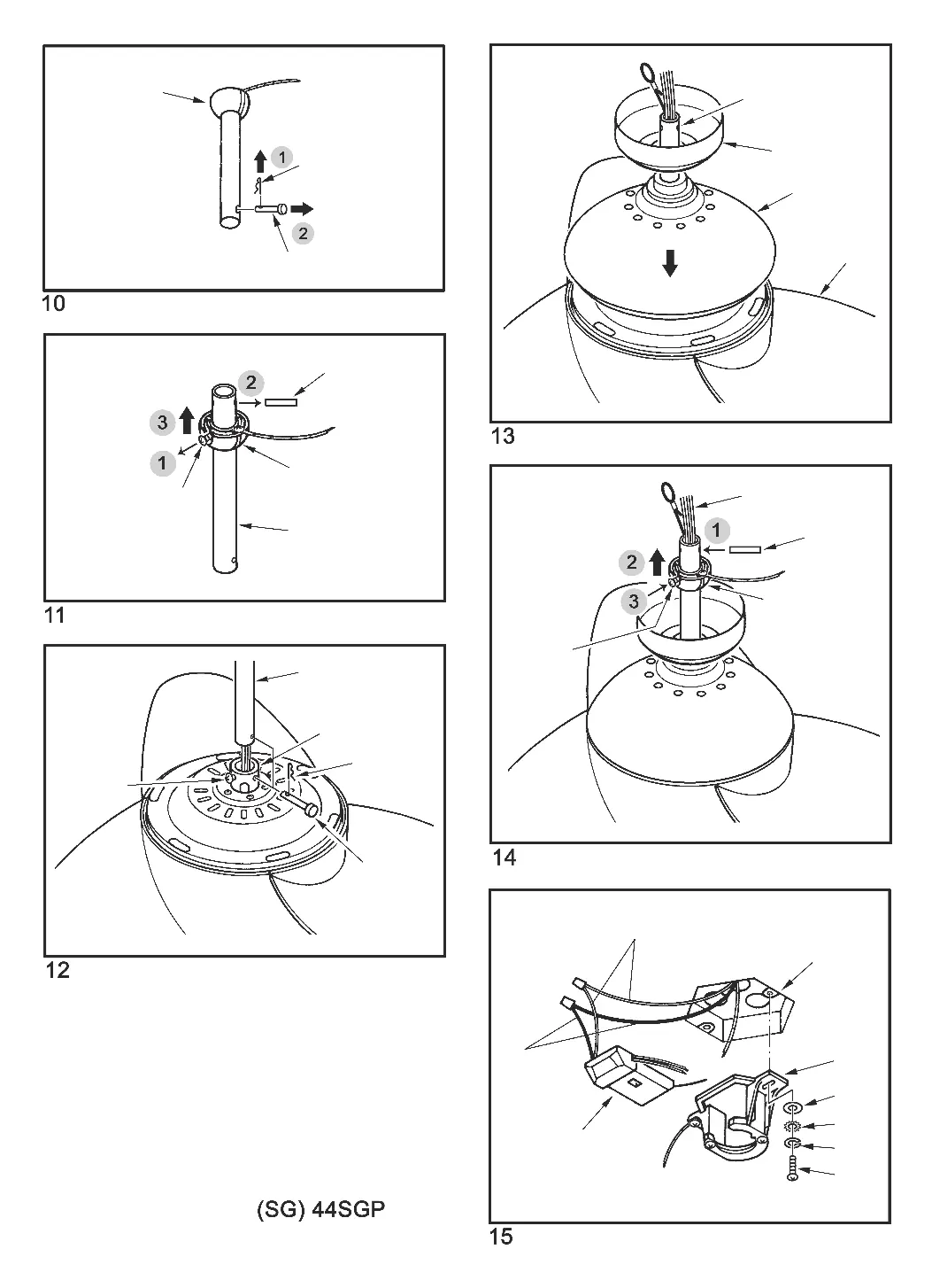
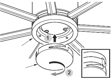
Mounting and Downrod: Ensure the outlet box is securely fastened to a structural ceiling member. Remove the preassembled keeper pin and cross pin from the downrod. Thread lead wires and safety cable through the downrod. Secure the downrod into the motor housing yoke using the cross pin and keeper pin, then tighten the set screws. Install the ball end of the downrod into the mounting bracket, ensuring the slot on the ball aligns with the tab on the bracket.
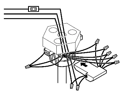
Wiring: Connect the wires using the provided connectors. Connect Red, Purple, and Gray wires from the fan to the corresponding wires on the remote receiver. Connect Blue and White wires from the fan to the receiver. Connect the house power (White/Neutral and Black/Live) to the receiver's AC IN N and AC IN L terminals. Connect all green ground wires to the house ground wire.
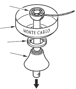
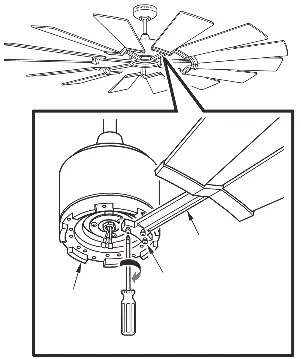
Blades and Light Kit: Install blades by aligning holes with the blade bracket and securing with provided setscrews and washers. Attach the blade assembly to the motor. For the light kit, attach the light pan to the motor plate, then connect the LED module wires (White to White, Blue/Black to Blue/Black) and attach the LED light kit. If not using the light, install the blanking plate instead.
Remote Control Operation
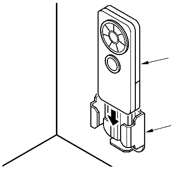
Universal vs. Learning Mode: Use the dip switch inside the remote battery compartment to select the mode. Universal Mode (UPPER position) allows control by any remote with the same setting. Learning Mode (LOWER position) pairs the remote to a specific fan.
Pairing: To pair in Learning Mode, turn the power on for the specific fan only. Within 60 seconds of restoring power, press and hold the LEARN button for at least 3 seconds. The light will twinkle twice to confirm pairing.
Dimming: The remote is factory-set to dimming mode. Use the DIM/ON switch to toggle between dimming (DIM) and non-dimming (ON) functions.
Troubleshooting
If the fan does not start, check circuit fuses, line wire connections, and remote dip switch settings. If the fan is noisy, ensure all screws in the motor housing are snug and allow a 24-hour break-in period. If the fan wobbles, ensure the mounting bracket is secure and blade levels are equal; use the provided balancing kit if necessary.
Practical help
Common problems
Fan does not start
Check main/branch circuit fuses, verify line wire connections, ensure the wall switch is not in the middle position, and check remote dip switch settings and battery.
Fan sounds noisy
Check that all motor housing screws are snug, wire nut connectors are not rattling, and the lightbulb is tight. Allow a 24-hour break-in period.
Fan wobbles
Ensure the mounting bracket ridge engages the downrod ball notch. Check that all blade holders are tight. If wobble persists, use the provided balancing kit.
Light does not work
Check blue wire connection to the hot wire, verify loose wires in the switch housing, check for a faulty bulb, and ensure the remote dip switches are correct.
Before use
- Turn off power at the service panel.
- Ensure the outlet box is marked 'Acceptable for Fan Support of 35 lbs or less'.
- Verify the ceiling angle is not steeper than 20 degrees for angle mounts.
- Ensure the fan blades have at least 7 feet of clearance from the floor.
- Install 2x 1.5V AAA batteries in the remote.
Specs in practice
- Universal Mode
- Allows the fan to be controlled by any remote transmitter with the same dip switch setting.
- Learning Mode
- Pairs the remote transmitter specifically to one fan, preventing interference from other remotes.
- Dimming Function
- Allows the light to cycle from bright to dim to bright; can be disabled by switching to 'ON' mode.
Images and diagrams
- The wiring diagram illustrates the connections between the house power source, the remote receiver, and the fan motor/light kit.
- The downrod assembly diagram shows the correct insertion of the cross pin and keeper pin.
Model compatibility
- Suitable for damp locations (covered patios or porches).
- Do not use with any other solid-state fan speed control device.
- Must be installed with a general use, isolating wall control/switch.

Manual page author
Emily Carter
User documentation editor
Prepares concise manual descriptions and highlights the most useful setup, operation, and maintenance information for readers.