Electronics / Amplifiers Receivers
User Manual for Vonyx VXA Series Power Amplifier
Quick guide for the Vonyx VXA Series power amplifier. Learn about front and rear panel controls, stereo and bridge mode setup, wiring connections, and safety precautions.
Table of contents
Manual images
Click an image to enlargeQuick Guide
The Vonyx VXA Series is a professional power amplifier designed for various audio applications. Before using the unit, ensure the mains voltage matches the 220-240Vac/50Hz requirement. Always turn the volume to the minimum before switching the amplifier on to prevent damage to speakers. Ensure the unit is placed in a well-ventilated area and never cover the ventilation holes.
Front Panel Controls
The front panel provides essential monitoring and control:
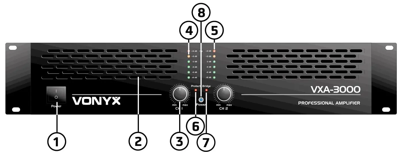
- On/Off Switch: Main power toggle.
- Volume Controls: Adjusts the output level for each channel.
- Signal Indicators: Three orange LEDs showing output signal levels.
- Clip Indication: Lights up when the channel is at maximum power. If lit continuously, reduce the volume immediately to avoid permanent damage.
- Protect Indication: Illuminates if the amplifier enters protection mode due to bad ventilation, low impedance (< 4 Ohm), defective fans, or short circuits.
- Power Indication: Blue LED indicating the unit is powered on.
Rear Panel Connections
The rear panel handles signal input and speaker output:
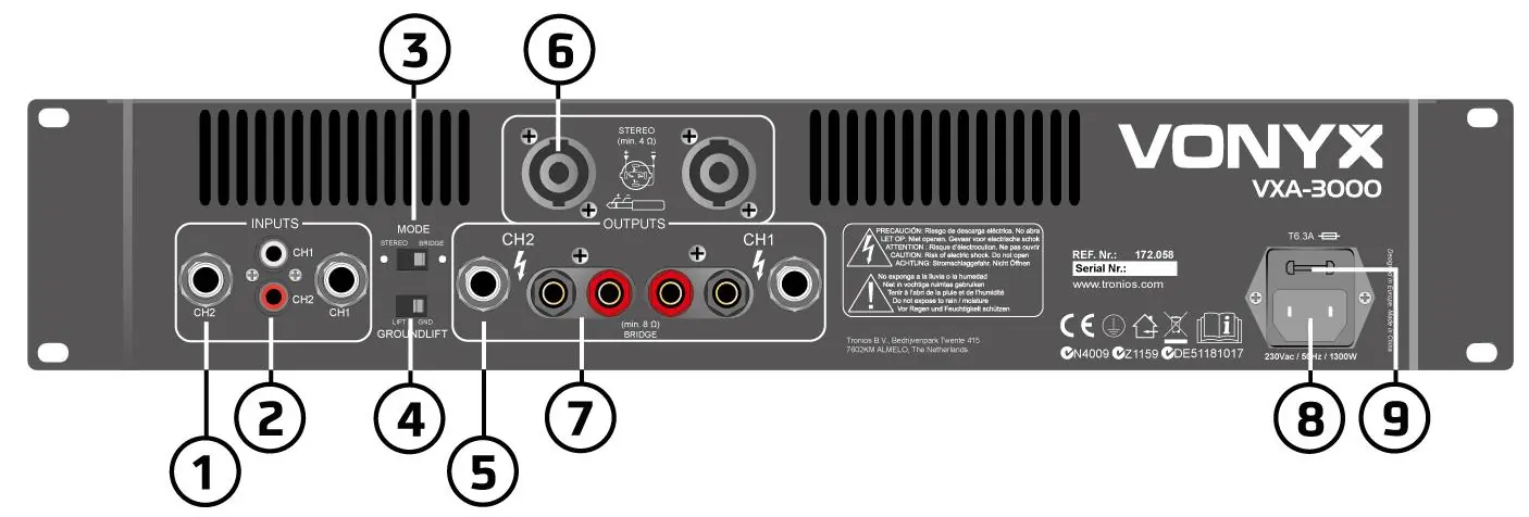
- Inputs: Features 6.3mm jack and RCA connectors for connecting signal sources like mixers.
- Mode Switch: Selects between Stereo and Bridge modes.
- Ground Lift Switch: Separates circuit and chassis grounds to eliminate hum caused by earth loops.
- Outputs: Includes 6.3mm jack, NL4, and binding post terminals for speaker connections.
Installation and Wiring
Ensure the amplifier is turned off before making any connections. The amplifier supports two operation modes:
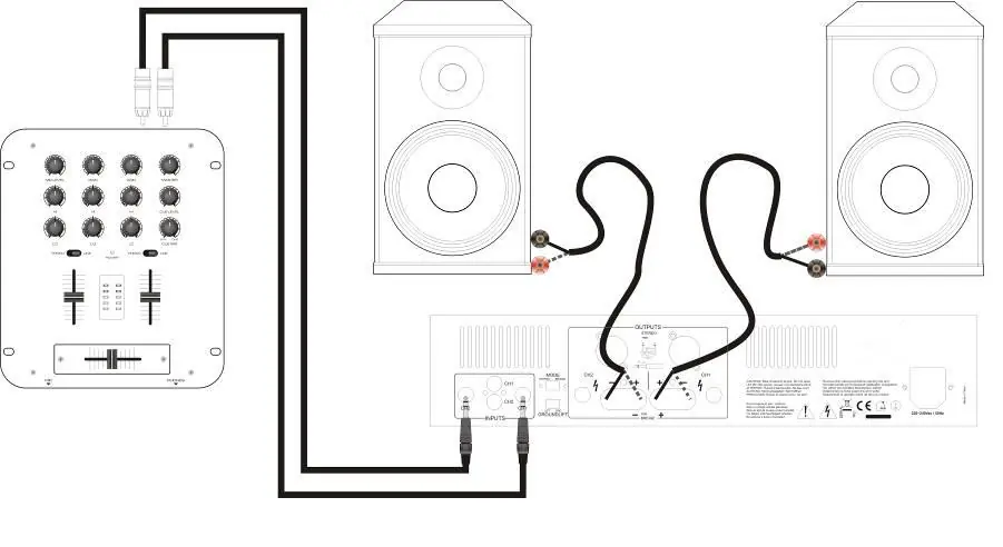
- Stereo Operation: Set the mode selector to 'stereo'. In this mode, the amplifier operates as two independent channels with separate volume controls.
- Bridge Operation: Set the mode selector to 'bridged'. This combines both channels into one for double the power. Connect the signal to the left input and use the left volume control. Connect the speaker across the positive (+) terminals only. Do not use the negative (-) terminals in this mode.
Wiring Guidelines: Use the appropriate wire size based on the distance between the amplifier and speakers: less than 10m requires 1.5mm², 10-20m requires 2.5mm², and 20-30m requires 4.0mm².
Technical Specifications
The VXA series includes models VXA-800, VXA-1200, VXA-1500, VXA-2000, and VXA-3000. Key specifications include a frequency range of 10Hz ~ 20kHz (±1.2dB), a damping factor greater than 250, and a signal-to-noise ratio greater than 90dB. Input sensitivity ranges from 775mV to 1.2V with an input impedance of 20kOhm.
Safety and Maintenance
Do not open the housing as it contains high-voltage parts. Clean the unit only with a dry cloth; do not use chemical sprays or cleaners. If the unit is not used for a long period, unplug it from the mains. If the unit has been stored in a cold environment, allow it to reach room temperature before switching it on to prevent condensation.
Manufacturer information
Vonyx
Practical help
Common problems
Protect LED is lit
Check for bad ventilation, low impedance (< 4 Ohm), defective fans, or short circuits in cables.
Clip LED is lit continuously
Reduce the volume immediately to prevent permanent equipment damage.
Humming noise
Use the Ground Lift switch on the rear panel to separate circuit and chassis grounds.
Before use
- Ensure mains voltage is 220-240Vac/50Hz.
- Turn volume controls to minimum before switching on.
- Check that speakers are compatible with the amplifier's impedance.
- Ensure adequate ventilation around the unit.
- Verify all cable connections are secure and correct.
Specs in practice
- Damping Factor >250
- Indicates the amplifier's ability to control speaker cone movement.
Images and diagrams
- Front panel: Power switch, volume knobs, and status LEDs (Signal, Clip, Protect, Bridge, Power).
- Rear panel: Input jacks (RCA/6.3mm), Mode switch, Ground Lift, and Output terminals (NL4/Binding Post).
Model compatibility
- Stereo mode: 4 Ohm minimum load per channel.
- Bridge mode: 8 Ohm minimum load.

Manual page author
Emily Carter
User documentation editor
Prepares concise manual descriptions and highlights the most useful setup, operation, and maintenance information for readers.