Music / Guitar Effects
User Manual for Walrus Audio MERAKI Analog Stereo Delay Pedal
Comprehensive user guide for the Walrus Audio MERAKI Analog Stereo Delay Pedal. Includes setup instructions, control explanations, MIDI implementation, internal dip switch configurations, and technical specifications.
Table of contents
Manual images
Click an image to enlargeQuick Start and Power
The Walrus Audio Meraki is a true stereo analog delay pedal featuring eight MN3005 chips. To power the pedal, use only a 9V DC, Center Negative, 500mA power supply. It is highly recommended to use an isolated power supply; daisy chain power supplies are not recommended.
Controls Overview
The Meraki features several knobs and switches to shape your delay sound:
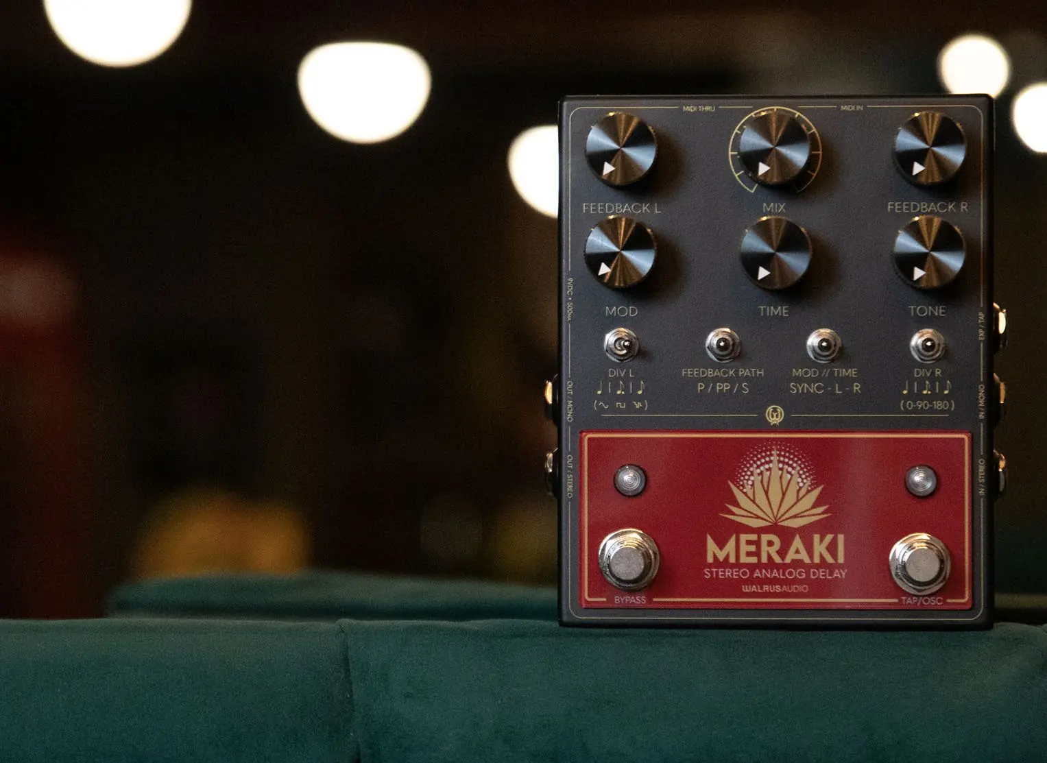
- Mix: Adjusts the overall level of repeats in both left and right channels. 50/50 mix is approximately at 2 o'clock.
- Feedback Left/Right: Adjusts the amount of repeats in the respective channel, from a single repeat to full oscillation.
- Mod (Mod Rate): Adjusts the depth of modulation. Hold the Bypass switch and use the Mod knob to adjust the mod rate.
- Time: Adjusts delay time from 80-1200ms. Clockwise for longer times, counter-clockwise for shorter.
- Tone: A Tilt EQ control. Clockwise cuts lows and boosts highs; counter-clockwise cuts highs and boosts lows.
- Tap Division Switches (Left/Right): Selects between quarter note, dotted eighth, and eighth note repeats.
- Bypass Switch: Turns the pedal on/off. Hold to access secondary controls.
- Tap Tempo Switch: Sets the delay time. Hold to maximize feedback (oscillation).
Feedback Modes
The Feedback Path switch allows you to choose between three delay line configurations:
- Parallel: Left and Right feedback paths are independent.
- Ping-Pong: Left repeats feedback into the right input, and right repeats into the left input, causing repeats to bounce between sides.
- Series: Left repeats feedback into the Left channel and is sent to the input of the Right delay line. Right repeats, with the addition of left repeats, feedback into the right input.
Advanced Settings and Internal Adjustments
The Meraki includes internal components for deeper customization:
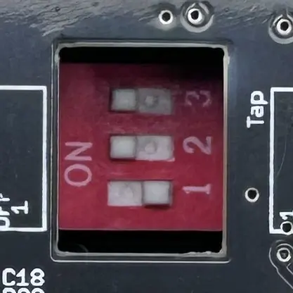
- Internal Dip Switches: Located inside the pedal. Configure these to switch between Tap Tempo or Expression pedal functionality.
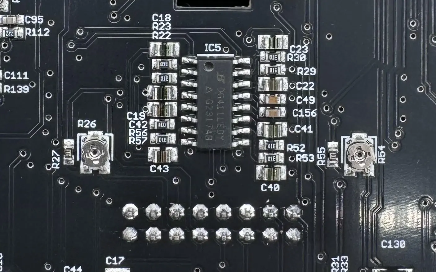
- Internal Trim Pots: Two trim pots (one for left, one for right) adjust how quickly the delay repeats go into self-oscillation. Turn clockwise to slow down oscillation, counter-clockwise to speed it up.
MIDI Implementation
The pedal supports MIDI control for digital parameters. To change the MIDI channel, hold down both stomp switches while applying power. The LEDs will flash; send a MIDI message on the desired channel to set it.
Technical Specifications
- Frequency Response: 60Hz to 20kHz
- Noise Floor: -94dBu (Dry), -86dBu (Wet)
- Input Impedance: ~1M Ohms
- Output Impedance: ~100 Ohms
- Power Requirement: 9V DC, 500mA
- Bypass Options: True bypass (no trails) or Buffered bypass (trails).
Practical help
Common problems
Pedal not oscillating correctly
Adjust the internal trim pots on the circuit board to control how quickly the pedal enters self-oscillation.
Expression pedal not functioning
Ensure the internal dip switches are set correctly for Expression mode (1 OFF, 2 ON, 3 ON).
MIDI channel configuration
Hold both stomp switches while applying power, then send a MIDI message on the desired channel to assign it.
Before use
- Use a 9V DC, Center Negative, 500mA power supply.
- Use an isolated power supply; avoid daisy chains.
- Determine if you need Buffered (trails) or True Bypass (no trails) mode.
- Configure internal dip switches if using an external expression pedal.
Specs in practice
- Frequency Response
- 60Hz to 20kHz, covering the full audible spectrum.
- Input Impedance
- ~1M Ohms, standard for guitar instrument inputs.
- Power Requirement
- 9V DC, 500mA; ensure your power supply meets this current draw.
Images and diagrams
- Internal Dip Switches: Located on the PCB; used to toggle between Tap and Expression pedal modes.
- Internal Trim Pots: Two pots located on the PCB to calibrate the self-oscillation speed for Left and Right channels.
Model compatibility
- Supports MIDI control for all digital parameters.
- Supports external expression pedal for time or modulation depth control.

Manual page author
Emily Carter
User documentation editor
Prepares concise manual descriptions and highlights the most useful setup, operation, and maintenance information for readers.