HVAC / Thermostats & Controls
White-Rodgers 1E30-373 Low Voltage Thermostat User Manual
A comprehensive user guide for the White-Rodgers 1E30-373 Low Voltage Thermostat. Includes detailed instructions for installation, wiring, heat-anticipator adjustment, and calibration procedures.
Quick answers from the manual
Quick answer
- The 1E30-373 is a low voltage thermostat. Installation requires mounting on an interior wall, routing wires, and connecting to the heating system. It features an adjustable heat anticipator and calibration adjustment. p. 1, 2
Key actions
- Adjusting the heat anticipator p. 2
- Calibrating the thermostat p. 2
Problems and fixes
Cycles too long
Set adjustable heater to a slightly lower dial setting.
p. 2
Cycles too short
Set adjustable heater to a slightly higher dial setting.
p. 2Technical specifications
| Parameter | Value | Meaning | Pages |
|---|---|---|---|
| Switch Rating | 1.0A at 30Vac max | Maximum electrical load capacity | p. 1 |
| Heating Anticipator | .15 to 1.0A | Adjustable range for primary control | p. 1 |
Where to find it in the PDF
- Installation and Specifications p. 1
- Adjustments and Calibration p. 2
Table of contents
Manual images
Click an image to enlargeImportant Information
The White-Rodgers 1E30-373 is a low voltage room thermostat designed for various types of heating plants. It features an adjustable heater that can be calibrated to the primary control's current rating. This document provides essential guidance on installation, wiring, and maintenance.
Selecting the Location
Proper placement is critical for accurate temperature control. Follow these guidelines:
- Install the thermostat approximately 5 feet above the floor.
- Mount on an interior partition wall; avoid outside walls.
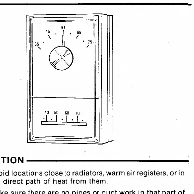
- Do not install near radiators, warm air registers, or in the direct path of heat.
- Avoid locations exposed to direct light from lamps, fireplaces, or other heat sources.
- Ensure the location is not in a room that is significantly warmer or cooler than the rest of the home.
Routing Wires
- Before drilling, use a small guide hole to check for obstructions.
- Probe for obstructions in the partition.
- Drill a 1/2" hole through the wall at the selected location.
- If there is no basement, drop the cable from the ceiling and snag it at the thermostat location.
- Attach the thermostat cable to the cord and pull it through the hole in the wall so that 6 inches of cable protrudes.
Mounting the Thermostat
- Pull the thermostat wires through the large hole in the center of the mounting plate.
- Fasten the wires beneath the two terminal screws on the bottom side of the plate.
- Push excess wire into the wall or switch box and plug the hole to prevent drafts from affecting the thermostat.
- Level the mounting plate and mark the holes for mounting screws.
- Attach the plate loosely to the wall with two screws, adjust for level, and tighten.
- Remove the cover from the thermostat base by pulling outward.
- Remove and discard the shipping protection for the switch.
- Place the thermostat base onto the mounting plate and tighten all three captive screws.
- Install the thermostat cover and secure it with the four provided allen screws using the included wrench to prevent tampering.
Wiring
All wiring must comply with local and national electrical codes and ordinances. Because of the many possible uses for these room thermostats, no specific wiring diagrams are provided. Use the wiring diagram that is packed with the primary control or the one supplied by the manufacturer of the heating equipment.
Heat-Anticipator Adjustment
The thermostat is equipped with an adjustable heater. Set the heater indicator to match the current rating of the primary control (adjustable from .15 to 1.0 Amps).
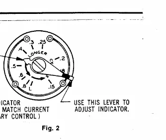
- Cycles too long: Set the adjustable heater to a slightly lower dial setting (1/2 division).
- Cycles too short: Set the adjustable heater to a slightly higher dial setting (1/2 division).
Calibration Adjustment
These thermostats are carefully adjusted at the factory and should not require re-calibration. If re-calibration is necessary:
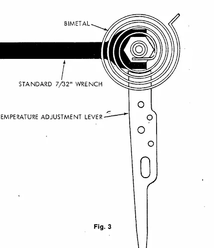
- Move the temperature adjustment lever to a setting about 5° above room temperature.
- Remove the thermostat cover.
- Slip a standard 7/32" wrench onto the hex nut beneath the bimetal.
- Hold the temperature adjustment lever stationary and turn the hex nut clockwise until the mercury shifts to the right end of the tube.
- Move the temperature adjustment lever to the lowest setting.
- Replace the thermostat cover and wait 10 minutes for the bimetal to stabilize.
- Move the temperature adjustment lever to correspond to the actual room temperature.
- Remove the cover, slip the 7/32" wrench onto the hex nut, and hold the lever stationary.
- Turn the hex nut counterclockwise until the mercury just barely shifts to the left end of the tube.
- Replace the cover and set the thermostat to the desired temperature.
Technical Specifications
- Switch Rating: 1.0A at 30Vac max.
- Heating Anticipator: .15 to 1.0A.
- Temperature Range: 35°F to 75°F.
Practical help
Common problems
Heating cycles are too long
Set the adjustable heater to a slightly lower dial setting (1/2 division).
Heating cycles are too short
Set the adjustable heater to a slightly higher dial setting (1/2 division).
Thermostat requires calibration
Follow the specific calibration procedure using a 7/32" wrench to adjust the hex nut beneath the bimetal.
Before use
- Ensure the thermostat is mounted on an interior wall.
- Verify the location is approximately 5 feet above the floor.
- Check that the location is not near radiators, warm air registers, or in direct heat paths.
- Ensure the wall is not an outside wall.
- Verify the primary control current rating is between .15 and 1.0 Amps.
Specs in practice
- Switch Rating
- 1.0A at 30Vac max; do not exceed this load.
- Heating Anticipator
- Adjustable from .15 to 1.0A to match the primary control.
- Temperature Range
- Operating range of 35°F to 75°F.
Images and diagrams
- Figure 1 illustrates the mounting plate, thermostat base, and cover assembly.
- Figure 2 shows the heat-anticipator adjustment dial and indicator.
- Figure 3 details the calibration adjustment lever, bimetal, and hex nut.
Model compatibility
- Designed for low voltage heating systems.
- Requires wiring diagram from the heating equipment manufacturer.

Manual page author
David Miller
Documentation analyst
Organizes user manual content into clear summaries, with attention to model details, product context, and everyday usability.