HVAC / Thermostats & Controls
Wiring Diagrams for White-Rodgers 1F95-1277 Universal Thermostat
Comprehensive wiring diagrams and installation guide for the White-Rodgers 1F95-1277 Universal Thermostat. Includes configurations for heat pumps, single-stage, and multi-stage heating/cooling systems.
Quick answers from the manual
Quick answer
- This document provides wiring diagrams for the White-Rodgers 1F95-1277 thermostat for various HVAC configurations, including heat pumps, single-stage, and multi-stage systems. p. 1
Key actions
- Configure thermostat settings in the Installer Configuration menu after wiring. p. 1
- Jumper W2 to W/E if the system lacks an E connection. p. 1
Problems and fixes
Backlight or remote sensor not working
Ensure 24V common connection is wired.
p. 1Where to find it in the PDF
- Heat Pump Wiring Diagrams p. 1
- Single/Multi-Stage Wiring Diagrams p. 1
Table of contents
Manual images
Click an image to enlargeQuick Guide from the Manual
This manual provides essential wiring diagrams for the White-Rodgers 1F95-1277 Universal Thermostat. It covers configurations for heat pump systems, as well as single-stage and multi-stage fossil fuel systems (gas, oil, or electric). Always refer to the equipment manufacturer's instructions for specific system wiring requirements.
Heat Pump Connections
The thermostat supports two types of heat pump systems:
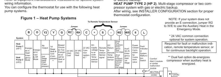
- HP1: Single stage compressor system with gas or electric backup.
- HP2: Multi-stage compressor or two-compressor system with gas or electric backup.
After wiring, you must configure the thermostat settings in the Installer Configuration menu.
Single and Multi-Stage Connections
For systems without a heat pump, the thermostat supports:
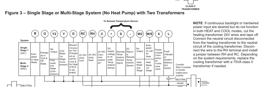
- SS1: Single stage gas, oil, or electric systems.
- MS2: Multi-stage gas, oil, or electric systems.
The diagrams provided in the manual distinguish between single-transformer and two-transformer system setups.
Important Configuration Notes
- Jumper Requirement: If your system lacks an 'E' connection, jumper W2 to W/E to enable Auxiliary Heat in Emergency Mode.
- 24V Common Connection: While optional for basic operation, it is required for fault/malfunction indication, remote temperature sensors, or continuous backlight operation.
- Dual Fuel Option: This setting de-energizes the compressor when auxiliary heat is energized.
- Backlight/Power Issues: If continuous backlight or hardwired power input is desired but does not function in both HEAT and COOL modes, you may need to modify the transformer wiring as described in the notes for two-transformer systems.
Practical help
Common problems
Auxiliary heat not working in Emergency Mode
If your system does not provide an 'E' connection, install a jumper between W2 and W/E.
Backlight or remote sensor not functioning
Ensure the 24V common connection is wired; it is required for these features.
Compressor runs during auxiliary heat
Ensure the Dual Fuel option is configured correctly, which de-energizes the compressor when auxiliary heat is active.
Before use
- Identify if your system is a Heat Pump (HP1/HP2) or Fossil Fuel (SS1/MS2) system.
- Determine if your HVAC system uses a single transformer or two transformers.
- Check if your system requires a 24V common connection for advanced features.
- Consult the equipment manufacturer's instructions for specific wiring requirements.
- Verify if a jumper is needed between W2 and W/E.
Images and diagrams
- Figure 1: Wiring diagram for Heat Pump systems.
- Figure 2: Wiring diagram for Single Stage or Multi-Stage systems with a single transformer.
- Figure 3: Wiring diagram for Single Stage or Multi-Stage systems with two transformers.
Model compatibility
- Compatible with single-transformer or two-transformer systems.
- Requires post-wiring configuration in the Installer Configuration menu.

Manual page author
Emily Carter
User documentation editor
Prepares concise manual descriptions and highlights the most useful setup, operation, and maintenance information for readers.