HVAC / Thermostats & Controls
Installation Instructions for White-Rodgers 1F97-51 Thermostat
A comprehensive installation and setup guide for the White-Rodgers 1F97-51 7-Day Electronic Digital Thermostat, including wiring diagrams, system configuration, and troubleshooting steps.
Quick answers from the manual
Quick answer
- The 1F97-51 is a 7-day programmable thermostat. Installation involves identifying your existing wiring type, mounting the subbase, and connecting wires according to the specific system diagrams provided in the manual. p. 1, 2, 3
Key actions
- Configure for Electric Heat p. 6
- Activate Energy Management Recovery (EMR) p. 6
- Override Compressor Lockout p. 7
First start
- Program the thermostat with batteries installed before attaching it to the subbase. p. 2
Problems and fixes
System does not function
Disconnect electrical power and check that all wiring is correct.
p. 6Maintenance and reset
- The thermostat uses three AA Energizer batteries to maintain the program during power failure. p. 1
Technical specifications
| Parameter | Value | Meaning | Pages |
|---|---|---|---|
| Electrical Rating | 17 to 30 VAC | Operating voltage range | p. 2 |
| Maximum Load | 1.5 Amps | Total load for all terminals combined | p. 2 |
Where to find it in the PDF
- Installation Instructions p. 1, 2, 3, 4
- Operation Guide p. 6, 7
Table of contents
Manual images
Click an image to enlargeQuick guide from the manual
The White-Rodgers 1F97-51 is a 7-day programmable, low-voltage thermostat. Before installation, ensure power is disconnected at the main fuse box. Program the thermostat with batteries installed before mounting it to the subbase. The device requires specific wiring configurations based on your heating/cooling system type (e.g., heat-only, cool-only, or heat/cool). Note that this model is not compatible with multi-stage or heat pump systems.
Description and Precautions
This wall-mounted thermostat maintains room temperature by controlling heating and cooling systems. It allows up to four time/temperature settings per 24-hour period. Precautions: All wiring must conform to local and national electrical codes. Do not exceed specification ratings (17-30 VAC, 1.5 Amps). If you are unsure about your wiring type (millivolt, line, or low voltage), consult a qualified contractor.
Installation
New Installation:
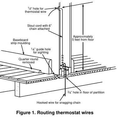
- Select a location about 5 feet above the floor on an interior partitioning wall.
- Avoid areas with direct sunlight, drafts, or poor air circulation.
- Route wires through the wall using a guide hole and a stout cord to pull wires through.
Replacement Installation:
- Shut off electricity and verify power is off with a voltmeter.
- Remove the old thermostat cover and wall plate.
- Use the provided self-adhesive labels to identify wires based on the old thermostat's terminal markings (refer to Table 1 and Table 2 in the manual).
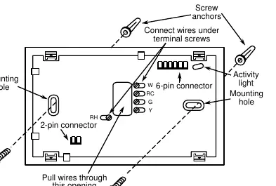
- Attach the new subbase to the wall using the provided mounting holes.
- Connect wires to the subbase terminals according to the appropriate wiring schematic.
Wiring Diagrams
The manual provides specific wiring diagrams for various system configurations:
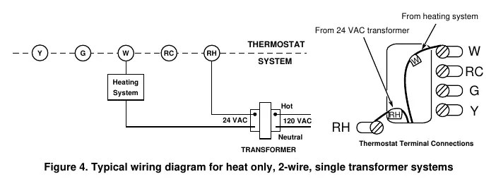
- Heat only (2-wire/3-wire): Single transformer systems.
- Cool only (3-wire): Single transformer systems.
- Heat/Cool (4-wire/5-wire): Single or two-transformer systems.
Always ensure the red jumper wire is connected between RH and RC terminals if required by your specific system configuration.
Operation and Configuration
System Configuration:
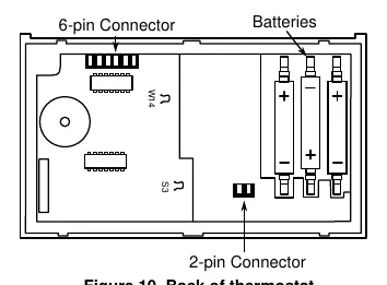
- Electric Heat Systems: If the blower is energized by a separate circuit through the fan relay, clip wire W14 on the back of the thermostat. Do not clip if energizing electric heat sequencers.
- Energy Management Recovery (EMR): This feature calculates the time needed to reach the set temperature by the start of the next program period. To activate, clip wire S3 on the back of the thermostat.
Fan and System Operation:
- Use the FAN SWITCH to toggle between FAN ON and FAN AUTO.
- Use the SYSTEM SWITCH to select HEAT or COOL modes.
Troubleshooting
If the system does not function correctly, disconnect power and verify all wiring. The thermostat includes a 5-minute compressor short-term cycle protection delay. If the 'COOL' indicator is flashing, the lockout feature is active. For further troubleshooting, refer to the Question & Answer section of the Operation Guide.
Practical help
Common problems
Thermostat not functioning
Disconnect power at the main fuse box and verify all wiring connections are correct.
Compressor will not start
Check if the 'COOL' indicator is flashing, indicating the 5-minute compressor lockout delay is active.
Blower does not operate
Ensure the G terminal is properly connected to the blower relay.
Before use
- Verify system voltage is between 17 and 30 VAC.
- Ensure power is disconnected at the main fuse box before starting installation.
- Program the thermostat with batteries installed before attaching to the subbase.
- Identify your old thermostat type using the provided identification tables.
- Ensure the red jumper wire is installed between RH and RC if required by your system.
Specs in practice
- Electrical Rating
- 17 to 30 VAC, 0.05 to 1.5 Amps (1.5A max total load).
- Setpoint Temperature Range
- 40°F to 99°F (4°C to 37°C).
- Operating Ambient Temperature
- 32°F to 105°F.
Images and diagrams
- Figure 1: Routing thermostat wires through the wall.
- Figure 3: Subbase terminal connections and mounting.
- Figures 4-8: Wiring diagrams for various heating/cooling system configurations.
- Figure 10: Location of W14 and S3 configuration wires on the back of the thermostat.
Model compatibility
- Not for use with multi-stage systems.
- Not for use with heat pump systems.
- Not for systems exceeding 30 VAC and 1.5 Amps.

Manual page author
Michael Turner
Technical manual editor
Reviews PDF manuals for structure, safety notes, and practical product details so readers can find the right information quickly.