HVAC / Thermostats & Controls
User Manual for White-Rodgers 1F97-1277 Thermostat
Quick guide for the White-Rodgers 1F97-1277 thermostat. Includes installation steps, wiring diagrams, programming instructions, configuration menu settings, and troubleshooting tips.
Quick answers from the manual
Quick answer
- The 1F97-1277 is a single-stage thermostat. Installation involves disconnecting power, labeling wires, mounting the base, and wiring according to the provided schematics. Configuration is done via the Installer Menu. p. 1, 2
Key actions
- Access Installer Configuration Menu p. 5
- Reset Thermostat p. 12
First start
- Remove battery tag, mount base, connect wires, and configure settings via the Installer Menu. p. 2, 5
Problems and fixes
No Heat/No Cool/No Fan
Replace fuse, reset breaker, turn furnace switch to ON, or tighten connections.
p. 12Maintenance and reset
- Reset thermostat by removing R/C wires and batteries for 2 minutes. p. 12
Technical specifications
| Parameter | Value | Meaning | Pages |
|---|---|---|---|
| Electrical Rating | mV to 30 VAC, NEC Class II, 50/60 Hz or DC | Power requirements | p. 1 |
| Setpoint Range | 45 to 99°F (7 to 37°C) | Temperature control range | p. 1 |
Where to find it in the PDF
- Installation and Wiring p. 2, 3
- Configuration Menu p. 5, 6, 7
- Programming p. 8, 9, 10
Table of contents
Manual images
Click an image to enlargeQuick Guide from the Manual
The White-Rodgers 1F97-1277 is a single-stage thermostat designed for gas, oil, electric, and hydronic heating/cooling systems. Before installation, ensure the power is disconnected at the main fuse or circuit breaker. The unit is powered by 2 AA batteries or hardwired 20-30 VAC. Key features include programmable schedules (7-day or 5/1/1), auto changeover, and remote temperature sensing capabilities.
Installation
To install the thermostat:
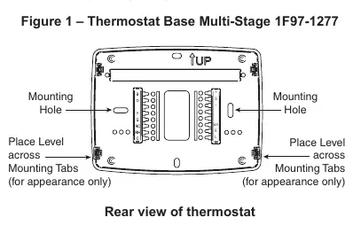
- Remove the old thermostat cover and base, labeling each wire with its terminal designation before disconnecting.
- Place the new base over the wall hole and mark mounting locations.
- Drill holes and use plastic anchors if necessary.
- Fasten the base to the wall.
- Connect wires to the terminal block according to the wiring diagrams.
- Push excess wire into the wall and plug the hole with fire-resistant material to prevent drafts.
- Snap the thermostat body onto the base.
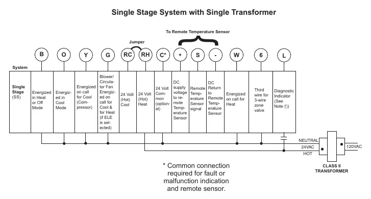
Wiring Connections
The thermostat supports single-transformer and two-transformer systems. Refer to the specific wiring diagrams in the manual for your system type. Ensure no bare wire sticks out from under the terminal block to prevent shorts.
Installer Configuration Menu
To access the configuration menu, press the Menu touch key, then press and hold the Installer Config touch key for 5 seconds. Use the arrow keys to navigate and change settings. Important settings include:
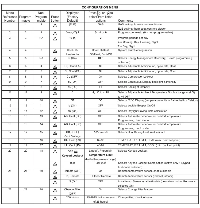
- GAS/ELE: Select GAS for furnace-controlled blower or ELE for thermostat-controlled blower.
- Programs per week: Configure for 7-day, 5/1/1, or non-programmable.
- System Switch: Configure for Heat/Cool, Heat Only, or Cool Only.
- Temperature Limits: Set maximum heat and minimum cool setpoints.
- Keypad Lockout: Set security levels (Total, Partial, or Temperature Limit).
Programming
You can program heating and cooling schedules for different periods (Morning, Day, Evening, Night). Use the Set Schedule button to enter programming mode. The Auto Schedule feature allows you to quickly set a comfort temperature for all periods with a 6°F setback for night periods.
Wired Remote Temperature Sensing
The thermostat supports one wired remote temperature sensor (indoor or outdoor). Connect the sensor to the +, S, and - terminals. Enable and configure the sensor in the Installer Configuration Menu.
Troubleshooting
If the thermostat is not functioning correctly, try the following:
- Reset: Remove wires from R and C, remove batteries for 2 minutes, then replace.
- No Heat/Cool: Check fuse/breaker, furnace power switch, and blower door.
- Runs Constantly: Check for shorted wiring or if the Fan switch is set to ON.
- Forgot Lockout Code: Press the Menu button and hold for 20 seconds to unlock.
Practical help
Common problems
No Heat/No Cool/No Fan
Check for a blown fuse or tripped circuit breaker. Ensure the furnace power switch is ON and the blower compartment door is properly installed.
Heat, Cool, or Fan runs constantly
Check for shorted wiring at the terminal block. Ensure the FAN switch is not set to ON.
Forgot Keypad Lockout Code
Press the Menu button and hold it for 20 seconds to unlock the thermostat.
Before use
- Disconnect electrical power at the main fuse or circuit breaker box.
- Label all wires with their terminal designation before removing the old thermostat.
- Remove the battery tag to engage the 2 AA batteries.
- Verify system compatibility (Single Stage gas, oil, electric, or hydronic).
Specs in practice
- Electrical Rating
- mV to 30 VAC, NEC Class II, 50/60 Hz or DC.
- Terminal Load
- 1.5A per terminal, 2.5A maximum for all terminals combined.
- Setpoint Range
- 45 to 99°F (7 to 37°C).
Images and diagrams
- Figure 1: Shows the thermostat base, mounting holes, and battery location.
- Wiring Diagrams: Illustrate connections for single-transformer and two-transformer systems.
Model compatibility
- Not compatible with Heat Pumps (with Aux or Emergency Heat).
- Not compatible with systems with up to 3 stages heat/2 stages cool.
- Compatible with 2-wire or 3-wire hydronic zone heat.

Manual page author
Emily Carter
User documentation editor
Prepares concise manual descriptions and highlights the most useful setup, operation, and maintenance information for readers.