HVAC / Thermostats & Controls
User Manual for White Rodgers 1F95-1277 Big Blue Universal Thermostat
Comprehensive user guide for the White Rodgers 1F95-1277 Big Blue Universal Thermostat. Includes installation instructions, wiring terminal descriptions, configuration menu settings, programming steps, and troubleshooting.
Quick answers from the manual
Quick answer
- The 1F95-1277 is a programmable thermostat for single-stage, multi-stage, and heat pump systems. It features a touchscreen interface, auto changeover, and remote sensor support. p. 1
Key actions
- Enter Installer Menu p. 4
- Reset Thermostat p. 11
First start
- Remove battery tag, mount base, connect wires according to diagram, and configure settings via the Installer Menu. p. 2, 4
Problems and fixes
Forgot Keypad Lockout Code
Press the menu button and hold in for 20 seconds.
p. 11Maintenance and reset
- To reset programming, press and hold the Menu and System buttons simultaneously. p. 11
Technical specifications
| Parameter | Value | Meaning | Pages |
|---|---|---|---|
| Setpoint Range | 45 to 99°F (7 to 32°C) | Adjustable temperature range. | p. 1 |
Where to find it in the PDF
- Installation p. 2
- Installer Configuration Menu p. 4, 5, 6
- Programming p. 7, 8, 9, 10
- Troubleshooting p. 11
Table of contents
Manual images
Click an image to enlargeQuick Start Guide
The White Rodgers 1F95-1277 is a programmable thermostat designed for single-stage, multi-stage, and heat pump systems. To begin, remove the battery tag to engage the batteries. Ensure the system power is off at the main breaker before installation. Use the Installer Configuration Menu to set up your specific system type (e.g., Heat Pump, Gas, Electric) and preferences.
Installation
Battery Location: The thermostat uses 2 "AA" alkaline batteries. Remove the thermostat body from the base to access the battery compartment on the rear.
Mounting: Pull the thermostat body off the base. Use the base as a template to mark mounting holes on the wall. Drill holes, insert anchors if necessary, and fasten the base to the wall. Leveling is for appearance only.
Wiring Connections
Refer to the terminal designation descriptions to connect your system wires correctly:
- B: Changeover valve (heat pump, energized in heating)
- O: Changeover valve (heat pump, energized in cooling/off)
- Y2: 2nd Stage Compressor
- Y: Compressor Relay
- G: Fan Relay
- RC: Power for Cooling
- RH: Power for Heating
- C: Common wire (optional, for backlight/remote sensor)
- W/E: Heat Relay/Emergency Heat Relay (Stage 1)
- W2: 2nd Stage Heat
Installer Configuration Menu
To enter the menu, press the Menu touch key, then press and hold the Installer Config touch key for 5 seconds. Use the arrow keys to navigate and change settings. Key settings include:
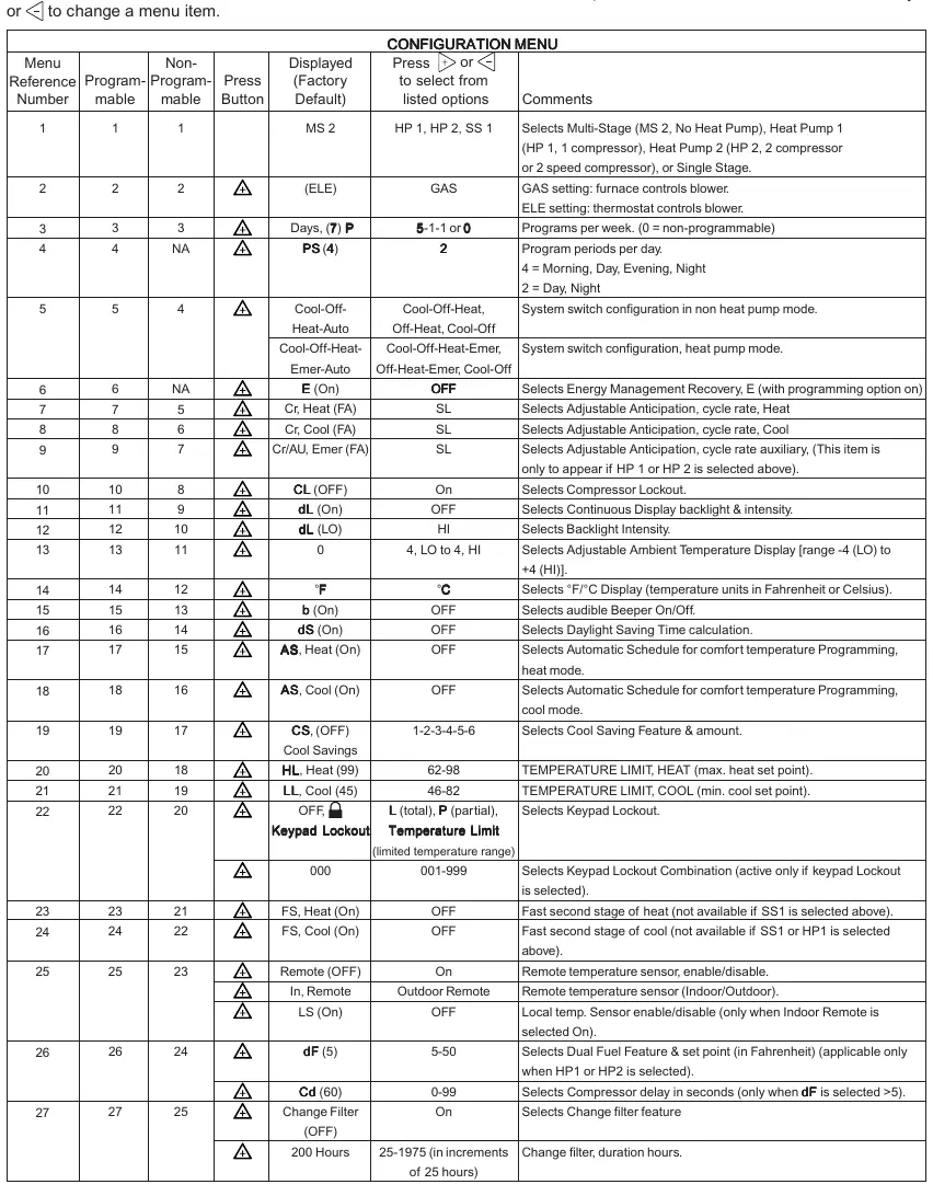
- Menu 1: Select system type (Multi-Stage, Heat Pump, Single Stage).
- Menu 3: Programs per week (7-day, 5/1/1, or non-programmable).
- Menu 4: Program steps per day (4 or 2).
- Menu 22: Keypad Lockout settings.
- Menu 25: Remote temperature sensor configuration.
Programming
Set Time and Day: Press the Menu key, then Set Time. Use arrow keys to adjust the hour, minutes, year, month, and date. Press Run Schedule to finish.
Heating/Cooling Programs: Press Menu, then Set Schedule. Select the system mode (Heat/Cool). Use arrow keys to set the temperature and time for each period (Morning, Day, Evening, Night). Use the Copy button to duplicate schedules across days.
Troubleshooting
If the thermostat displays erratic behavior or blanks out, perform a reset by removing the wires from terminals R and C and removing the batteries for 2 minutes. To reset programming, press and hold the Menu and System buttons simultaneously.
Practical help
Common problems
No Heat/No Cool/No Fan
Check for a blown fuse or tripped circuit breaker. Ensure the furnace power switch is ON and the blower door is properly closed. Tighten wiring connections.
Forgot Keypad Lockout Code
Press the Menu button and hold it for 20 seconds to unlock the thermostat.
Thermostat clicks but system does not start
Verify wiring connections. If the condition persists, contact an HVAC service professional to test the system.
Before use
- Remove the battery tag to engage the batteries.
- Disconnect electrical power at the main fuse or circuit breaker box.
- Label all wires with terminal designations before removing the old thermostat.
- Verify system compatibility (Heat Pump, Multi-Stage, etc.).
Specs in practice
- Electrical Rating
- mV to 30 VAC, NEC Class II, 50/60 Hz or DC.
- Terminal Load
- 1.5A per terminal, 2.5A maximum for all terminals combined.
- Setpoint Range
- 45 to 99°F (7 to 32°C).
- Operating Ambient
- 32°F to +105°F (0 to +41°C).
Images and diagrams
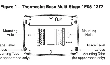
- Figure 1: Shows the thermostat base, mounting holes, and battery location.
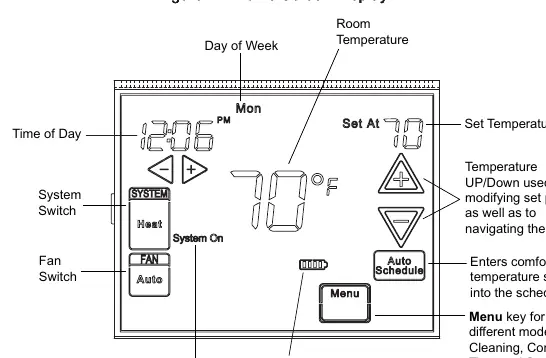
- Figure 2: Illustrates the home screen display, including time, temperature, and system status icons.
- Figure 3: Details the programming and configuration buttons layout.
Model compatibility
- Compatible with Heat Pump (with/without Aux), Multi-Stage (up to 3 heat/2 cool), Gas/Oil/Electric, and Hydronic systems.

Manual page author
Michael Turner
Technical manual editor
Reviews PDF manuals for structure, safety notes, and practical product details so readers can find the right information quickly.