HVAC / Thermostats & Controls
Installation Guide for White-Rodgers 1F91-71 Multi-stage Electronic Digital Thermostat
Comprehensive installation and setup guide for the White-Rodgers 1F91-71 multi-stage electronic digital thermostat. Includes wiring diagrams, system configuration, and troubleshooting steps.
Quick answers from the manual
Quick answer
- The 1F91-71 is a multi-stage electronic digital thermostat. Installation involves mounting the subbase, connecting wires according to the schematic, setting option switches, and attaching the thermostat unit. p. 1, 2, 3, 4
Key actions
- Install 9V battery p. 1, 6
- Set Option Switches p. 6
First start
- Turn on power, set system to HEAT or COOL, and adjust temperature to test stages. p. 7
Problems and fixes
Compressor short cycle protection
Wait 5 minutes for the thermostat to allow compressor operation.
p. 7Maintenance and reset
- Remove 9V battery for 2 minutes when changing option switches. p. 6
Technical specifications
| Parameter | Value | Meaning | Pages |
|---|---|---|---|
| Electrical Rating | 20-30v AC 50/60 Hz | Operating voltage | p. 2 |
| Max Load | 2.5 Amps | Total load for all terminals combined | p. 2 |
Where to find it in the PDF
- Installation Instructions p. 1, 2, 3, 4
- Wiring Diagrams p. 4, 5
- Operation & Configuration p. 6, 7
Table of contents
Manual images
Click an image to enlargeQuick Guide
This thermostat is a precision instrument designed for multi-stage heating and cooling systems. Before installation, ensure you have a 9V Energizer battery to maintain program settings during power failures. Always disconnect power at the main fuse box before beginning installation to prevent electrical shock.
Description
The 1F91-71 is a wall-mounted, low-voltage thermostat that supports up to three stages of heat and two stages of cool. It features indicator lights for system status and allows for four time/temperature settings per 24-hour period, with separate programs for weekdays and weekends.
Installation
New Installation:
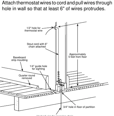
- Select a location about 5 feet above the floor on an interior partition wall.
- Avoid areas with direct sunlight, drafts, or poor air circulation.
- Route wires to the location by drilling a 1/2" hole in the wall and a 3/4" hole in the floor/ceiling as needed.
- Pull at least 6 inches of wire through the wall.
Replacement Installation:
- Shut off electricity and verify power is off with a voltmeter.
- Remove the old thermostat cover and wall plate.
- Identify each wire using the provided labels and record them in the terminal reference table.
- Disconnect wires and install the new subbase.
Wiring
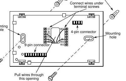
The thermostat requires both the hot and common sides of the 24vAC transformer to be present. Connect wires beneath the terminal screws on the subbase according to the wiring schematics provided in the manual (Figures 4, 5, and 6). Ensure all wiring conforms to local and national electrical codes.
System Configuration
Before attaching the thermostat to the subbase, set the option switches on the back of the unit:
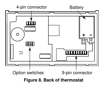
- Multi-stage Systems: Switch #1 ON, Switch #2 OFF.
- Electric Heat Systems: Switch #1 ON, Switch #2 ON.
- Economizer: Switch #3 ON.
- Automatic Changeover: Switch #4 ON.
Note: Any time an option switch is changed, the 9V battery must be removed for at least 2 minutes.
Operation and Testing
After installation, turn on the power. Use the FAN switch to test the blower. Use the SYSTEM switch to select HEAT or COOL and adjust the temperature to verify that all stages activate. The thermostat includes a 5-minute short-cycle protection delay to protect the compressor.
Troubleshooting
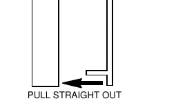
If the compressor does not start, it may be locked out by the 5-minute short-cycle protection. If the thermostat does not attach easily to the subbase, ensure the connector pins and plastic snaps are properly aligned and that excess wire is pushed into the wall.
Practical help
Common problems
Thermostat does not attach easily to subbase
Ensure connector pins and plastic snaps are aligned and excess wire is pushed into the wall.
Compressor does not start immediately
The thermostat has a 5-minute short-cycle protection delay. Wait for the delay to expire.
Program settings lost during power failure
Ensure a 9V Energizer battery is installed.
Before use
- Disconnect power at the main fuse box.
- Verify power is off with a voltmeter.
- Install a 9V battery for program backup.
- Set option switches before attaching to the subbase.
- Ensure both hot and common sides of the 24vAC transformer are present.
Specs in practice
- Electrical Rating
- 20 to 30v AC 50/60 Hz.
- Staging Data
- Supports up to 3 heating stages and 2 cooling stages.
- Setpoint Temperature Range
- 40°F to 99°F (4°C to 37°C).
Images and diagrams
- Figure 1: Routing thermostat wires through the wall.
- Figure 3: Subbase layout and terminal connections.
- Figure 4-6: Wiring diagrams for single and two-transformer systems.
Model compatibility
- Requires both hot and common sides of the 24vAC transformer.

Manual page author
David Miller
Documentation analyst
Organizes user manual content into clear summaries, with attention to model details, product context, and everyday usability.