HVAC / Thermostats & Controls
Installation and User Manual for White Rodgers 1E78 5/2 Day Programmable Thermostat
Comprehensive installation and programming guide for the White Rodgers 1E78 5/2 Day Programmable Thermostat. Includes wiring diagrams, jumper settings, and troubleshooting steps.
Quick answers from the manual
Quick answer
- The White Rodgers 1E78 is a 5/2 day programmable thermostat. Installation requires disconnecting power, labeling wires, and following the specific wiring diagram for your system type. Programming involves setting the time, day, and desired heating/cooling schedules. p. 1, 5
Key actions
- Reset the thermostat p. 6
- Disable EMR p. 2
- Change to Celsius p. 2
First start
- Install 2 AAA batteries, mount the base, connect wires according to the diagram, and set the time/day. p. 2, 5
Problems and fixes
Blank display
Replace batteries or perform a reset.
p. 6, 7Maintenance and reset
- Press Up, Down, and TIME buttons simultaneously to reset to factory defaults. p. 6
Technical specifications
| Parameter | Value | Meaning | Pages |
|---|---|---|---|
| Electrical Rating | MV to 30 VAC | Operating voltage range | p. 6 |
Where to find it in the PDF
- Preparations and Wiring p. 1, 2
- Programming p. 5, 6
- Troubleshooting p. 6, 7
Table of contents
Manual images
Click an image to enlargeQuick guide from the manual
The White Rodgers 1E78 is a 5/2 day programmable thermostat designed for 24V heating and cooling systems. This guide covers the essential steps for installation, wiring, and programming. Always ensure power is disconnected at the main fuse box before beginning installation.
Thermostat Details and Preparation
Before installing, ensure your system is compatible. This thermostat works with standard heat/cool systems, heat pumps (no aux/emergency heat), and hydronic systems. It is not compatible with multistage systems or line voltage (110/240V) systems.
Tools required: Hand or power drill with 3/16 inch bit, flat blade screwdriver, and wire cutter/stripper.
Installation and Wiring
Removing the old thermostat: Label each wire with its terminal designation before disconnecting. Do not let wires fall back into the wall.
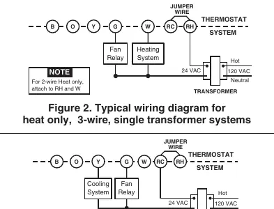
Mounting: Remove the thermostat body from the base. Use the base as a template to mark mounting holes. Fasten the base to the wall, ensuring it is level. Connect wires to the terminal screws according to the specific wiring diagram for your system (see Figures 2-7 in the manual).
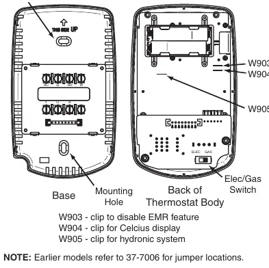
Jumper Settings: The circuit board contains jumpers for specific configurations:
- W903: Clip to disable Energy Management Recovery (EMR).
- W904: Clip to change display to Celsius.
- W905: Clip for hydronic (hot water/steam) systems to increase cycle time.
Operation and Programming
Batteries: The unit requires 2 AAA alkaline batteries. If the low battery icon appears, replace them immediately.
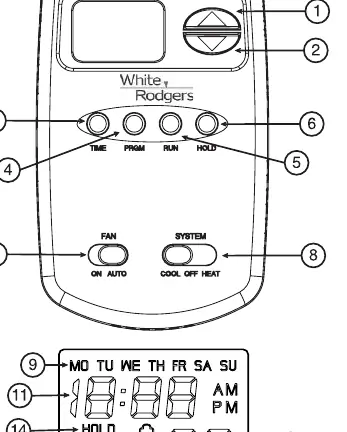
Programming: You can program heating and cooling schedules for weekdays (5 days) and weekends (2 days). Use the PRGM button to enter programming mode, the TIME button to set the clock, and the arrow buttons to adjust settings. You can store heating and cooling programs simultaneously.
Temperature Override: Press the arrow buttons to temporarily override the programmed temperature until the next period begins.
Hold Temperature: Press the HOLD button to maintain a specific temperature indefinitely until you press RUN.
Troubleshooting
If the thermostat is not functioning correctly, try the following:
- Reset: Press the Up arrow, Down arrow, and TIME buttons simultaneously to reset to factory defaults.
- Blank Display: Replace batteries or perform a reset.
- No Heat/Cool: Check the system switch position, verify wiring connections, and ensure the furnace power switch is ON.
Practical help
Common problems
No heat or cooling
Check fuse/breaker, ensure system switch is set correctly, verify wiring, or perform a reset.
Display blank or keypad unresponsive
Replace batteries or perform a reset by pressing Up, Down, and TIME buttons simultaneously.
Thermostat cycles too fast
For hydronic systems, clip jumper W905 to increase cycle time.
Before use
- Ensure power is off at the main fuse box.
- Label all wires before disconnecting the old thermostat.
- Verify system compatibility (not for multistage or line voltage systems).
- Install 2 fresh AAA alkaline batteries.
Specs in practice
- Electrical Rating
- MV to 30 VAC 50/60 Hz or D.C.; 1.5 Amps max total load.
- Setpoint Range
- 45°F to 90°F (7°C to 32°C).
- Operating Ambient Temp
- 32°F to 105°F.
Images and diagrams
- Figure 1: Thermostat base and jumper locations (W903, W904, W905).
- Figures 2-7: Wiring diagrams for various system configurations (heat only, cool only, heat pump, etc.).
Model compatibility
- Not compatible with multistage systems or line voltage (110/240V) systems.
- Compatible with 24V gas, oil, electric, and heat pump systems.

Manual page author
David Miller
Documentation analyst
Organizes user manual content into clear summaries, with attention to model details, product context, and everyday usability.