HVAC / Thermostats & Controls
User Manual for White Rodgers 1F78-144 Non-Programmable Thermostat
Complete user guide for the White Rodgers 1F78-144 non-programmable thermostat. Includes installation steps, wiring diagrams, operation instructions, and troubleshooting.
Quick answers from the manual
Quick answer
- The 1F78-144 is a non-programmable thermostat for heating and cooling systems. It requires 2 AAA batteries and supports various wiring configurations (heat only, cool only, heat/cool, heat pump). p. 1, 4
Key actions
- Reset the thermostat p. 5
- Replace batteries p. 2
First start
- Install 2 AAA batteries, mount the base, connect wires, and set the SYSTEM switch to HEAT or COOL. p. 2, 3
Problems and fixes
No Heat/Cool
Check fuse/breaker, power switch, and door panel.
p. 5Maintenance and reset
- Reset operation: press up and down arrows simultaneously while moving SYSTEM switch from OFF to HEAT. p. 5
Technical specifications
| Parameter | Value | Meaning | Pages |
|---|---|---|---|
| Electrical Rating | 0 to 30 VAC 50/60 Hz. or D.C. | 1.5 Amps Maximum Total Load | p. 5 |
Where to find it in the PDF
- Installation p. 1, 2
- Wiring Diagrams p. 3
- Operation p. 4
- Troubleshooting p. 5, 6
Table of contents
Manual images
Click an image to enlargeQuick Guide
The White Rodgers 1F78-144 is a non-programmable thermostat designed for heating and cooling systems. It operates on 2 AAA alkaline batteries. Key features include simultaneous heating/cooling setpoint storage, Fahrenheit/Celsius convertibility, and a low battery indicator. Before installation, ensure your system is compatible (24V, not line voltage) and turn off power at the main fuse or circuit breaker.
Installation
Tools required: Flat blade screwdriver, wire cutter/stripper, and a drill with a 3/16 inch bit if needed.
Steps:
- Preparation: Turn off electricity at the main fuse box.
- Remove Old Thermostat: Label each wire with the terminal designation it was removed from before disconnecting. Do not let wires fall back into the wall.
- Mounting: Remove the packing material. Pull the cover straight off the base. Place the base over the wall hole, mark mounting holes, drill, and fasten the base to the wall.
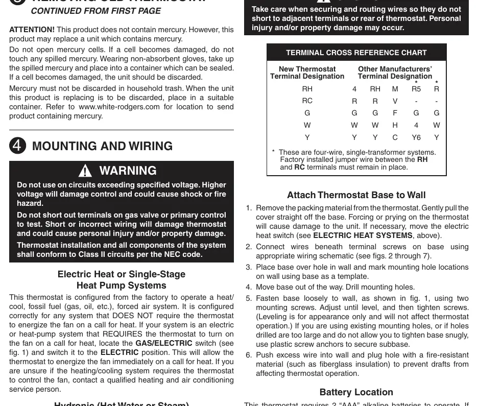
- Wiring: Connect wires beneath terminal screws on the base according to the provided wiring diagrams (Figures 2-7). Ensure wires do not short to adjacent terminals.
- Finishing: Push excess wire into the wall and plug the hole with fire-resistant material to prevent drafts.
Operation
The thermostat features a simple interface with up/down arrows for temperature adjustment, a FAN switch (ON/AUTO), and a SYSTEM switch (COOL/OFF/HEAT).
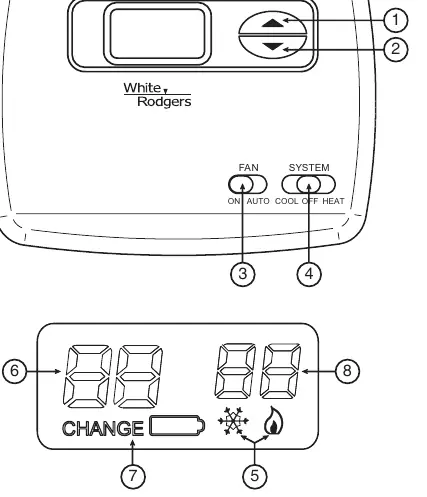
- Temperature Setting: Press the up or down arrow until the desired temperature is displayed.
- Display Backlight: Can be turned ON or OFF. With the system in HEAT mode, press the up and down arrows simultaneously for two seconds to access settings.
- F/C Conversion: Clipping the W904 jumper on the circuit board changes the display to Celsius.
- Low Battery: When the battery icon appears, replace the 2 AAA alkaline batteries.
Troubleshooting
If the thermostat does not function correctly, try a reset: press the up and down arrows simultaneously while moving the SYSTEM switch from OFF to HEAT. This resets factory defaults.
- No Heat/Cool/Fan: Check for a blown fuse or tripped circuit breaker, ensure the furnace power switch is ON, and verify the furnace blower door is properly closed.
- Cycles Too Fast/Slow: This may be due to thermostat location or system size. For hydronic systems, clipping jumper W905 may increase the cycle time.
- Blank Display: Replace batteries or perform a reset.
Specifications
Electrical Rating: 0 to 30 VAC 50/60 Hz or D.C., 1.5 Amps maximum total load.
Thermal Data: Setpoint range 45°F to 90°F (7°C to 32°C). Operating ambient temperature 32°F to 105°F (0°C to 41°C).
Humidity: 0 to 90% RH (non-condensing).
Practical help
Common problems
No Heat/No Cool/No Fan
Check fuse/breaker, ensure furnace power switch is ON, and verify furnace blower door is properly closed.
Furnace cycles too fast or too slow
Check thermostat location or system size. For hydronic systems, clipping jumper W905 may increase cycle time.
Blank display or keypad not responding
Replace batteries or perform a reset by pressing up and down arrows while moving SYSTEM switch from OFF to HEAT.
Before use
- Turn off power at the main fuse or circuit breaker.
- Label existing wires before disconnecting.
- Ensure system is 24V (not line voltage 110/240V).
- Install 2 AAA alkaline batteries.
- Verify system compatibility using the chart on page 1.
Specs in practice
- Electrical Rating
- 0-30 VAC, 1.5A max total load (all terminals combined).
- Setpoint Range
- 45°F to 90°F (7°C to 32°C).
- Operating Humidity
- 0-90% RH (non-condensing).
Images and diagrams
- Wiring diagrams cover various configurations including heat only, cool only, heat/cool, and heat pump systems.
- Ensure the red jumper wire is connected between RH and RC terminals if required by your system.
Model compatibility
- Not for line voltage (110/240V) systems.
- Not for multistage systems.
- Requires 2 AAA batteries.

Manual page author
Michael Turner
Technical manual editor
Reviews PDF manuals for structure, safety notes, and practical product details so readers can find the right information quickly.