HVAC / Thermostats & Controls
User Manual for White Rodgers 1F85-0422 Thermostat
Comprehensive user guide for the White Rodgers 1F85-0422 Blue Universal Thermostat. Includes installation instructions, wiring diagrams, configuration menu settings, programming steps, and troubleshooting advice.
Quick answers from the manual
Quick answer
- The 1F85-0422 is a universal thermostat for single-stage, multi-stage, or heat pump systems. It features programmable schedules, keypad lockout, and Comfort Alert diagnostics. p. 1
Key actions
- Access Installer Menu p. 4, 5
- Reset Thermostat p. 9
First start
- Install 2 AA batteries, mount the base, connect wires according to terminal designations, and configure settings via the Installer Menu. p. 2, 4
Problems and fixes
No Heat/Cool
Check power, fuse, and wiring connections.
p. 9
Comfort Alert Codes
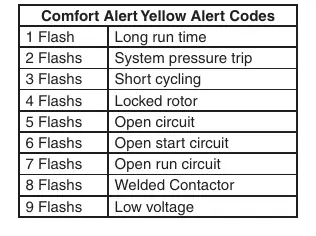
Refer to the table on page 8 for flash codes (e.g., 1 flash = Long run time).
p. 8Error codes
| Code | Meaning | Action | Pages |
|---|---|---|---|
| 1 Flash | Long run time | Check system | p. 8 |
| 2 Flashes | System pressure trip | Check system | p. 8 |
| 3 Flashes | Short cycling | Check system | p. 8 |
Maintenance and reset
- To reset the programming, clock and configuration settings, press and and the FAN button simultaneously. p. 9
Technical specifications
| Parameter | Value | Meaning | Pages |
|---|---|---|---|
| Setpoint Range | 45° to 90°F (7° to 32°C) | Temperature control range | p. 1 |
| Electrical Rating | mV to 30 VAC | Voltage compatibility | p. 1 |
Where to find it in the PDF
- Installation p. 2
- Installer Configuration Menu p. 4, 5
- Programming p. 7, 8
- Troubleshooting p. 8, 9
Table of contents
Manual images
Click an image to enlargeQuick Guide
The White Rodgers 1F85-0422 is a universal thermostat designed for single-stage, multi-stage, or heat pump systems. This guide covers installation, configuration, and daily operation. Always ensure the system power is disconnected before installation.
Installation
To install the thermostat:
- Remove the old thermostat cover and base, labeling wires before disconnecting.
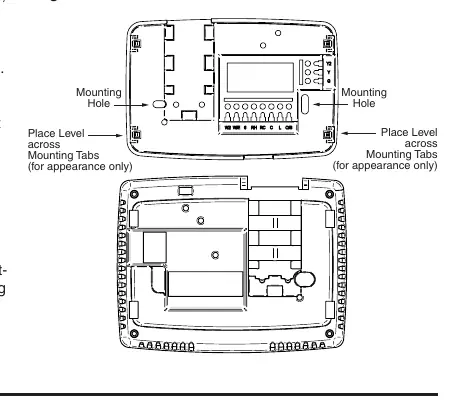
- Mount the new base using the provided holes as a template.
- Connect wires to the corresponding terminals on the base.
- Install 2 AA alkaline batteries.
- Snap the thermostat body onto the base.
Wiring Connections
Refer to the terminal designation descriptions to ensure correct wiring:
- L: Heat pump malfunction indicator.
- O/B: Changeover valve.
- Y/Y2: Compressor relay/2nd stage compressor.
- W/E: Heat relay/Emergency heat.
- W2: 2nd stage heat.
- G: Fan relay.
- RH/RC: Power for heating/cooling.
- C: Common wire.
Installer Configuration Menu
To access the configuration menu, ensure the thermostat is in Heat, Cool, or Auto mode, then press the MENU button for at least 5 seconds. Use the arrow keys to change options and the MENU button to advance to the next item. Key settings include:
- Item 1: Keypad Lockout.
- Item 2: System configuration (Multi-Stage, Heat Pump, Single Stage).
- Item 3: Fan operation (Gas or Electric).
- Item 4: Cool Savings feature.
- Item 6-8: Cycle rate selection.
- Item 10: System mode configuration.
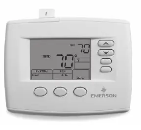
Operating Your Thermostat
Use the SYSTEM button to toggle between Heat, Off, Cool, Auto, and Emer modes. Use the FAN switch to select Auto (runs only when system is on) or On (continuous circulation). For programmable models, you can override the schedule by pressing the arrow keys and then the HOLD button.
Programming
To set the time and date, press MENU then TIME. Use the arrow keys to adjust. To program heating or cooling schedules, select the mode (Heat/Cool), press MENU, then SCHEDULE. Follow the on-screen prompts to set times and temperatures for the four daily periods (Wake Up, Leave For Work, Return Home, Go To Bed).
Troubleshooting
If the thermostat is not functioning correctly, try the following:
- Reset: Press and hold the FAN button while pressing the up and down arrows simultaneously.
- No Heat/Cool: Check for blown fuses, tripped breakers, or loose wiring.
- Comfort Alert Codes: If the thermostat displays "Call For Service" and the yellow LED flashes, refer to the Comfort Alert Yellow Alert Codes table on page 8 to identify the fault (e.g., 1 flash indicates long run time).
Practical help
Common problems
No Heat/No Cool/No Fan
Check for a blown fuse or tripped circuit breaker, ensure the furnace power switch is ON, and verify that the blower door is properly closed.
Thermostat Setting & Thermometer Disagree
Adjust the temperature display in the Configuration Menu (Item 12) to match your previous thermostat.
Forgot Keypad Lockout Code
Hold the MENU key for 20 seconds to reset the lockout.
Before use
- Label all wires before removing the old thermostat.
- Ensure the system power is turned off at the main fuse or circuit breaker.
- Install 2 fresh AA alkaline batteries.
- Review the Installer Configuration Menu to match your specific heating/cooling system.
- Verify wiring connections against the terminal designation list.
Specs in practice
- Electrical Rating
- mV to 30 VAC, NEC Class II, 50/60 Hz or DC.
- Setpoint Range
- 45° to 90°F (7° to 32°C).
- Terminal Load
- 1.5 A per terminal, 2.5A maximum combined.
- Operating Humidity
- 90% non-condensing max.
Images and diagrams
- Figure 1: Shows the battery door location and polarity.
- Figure 2: Illustrates the thermostat base, mounting holes, and terminal block.
- Figure 3: Explains the home screen display icons (System, Fan, Temperature).
- Figure 4: Details the programming and configuration icons.
Model compatibility
- Compatible with single-stage, multi-stage, and heat pump systems.
- Requires 2 AA alkaline batteries for operation or backup.
- Not compatible with systems exceeding 30 VAC.

Manual page author
David Miller
Documentation analyst
Organizes user manual content into clear summaries, with attention to model details, product context, and everyday usability.