HVAC / Thermostats & Controls
Installation and Operation Instructions for White-Rodgers 1F86-444 Thermostat
Quick guide for the White-Rodgers 1F86-444 non-programmable digital thermostat. Includes installation steps, wiring diagrams, operation instructions, and troubleshooting tips.
Quick answers from the manual
Quick answer
- The 1F86-444 is a non-programmable digital thermostat. It is powered by 3 AA batteries and is compatible with standard heat/cool, electric, gas, and single-stage heat pump systems. p. 1
Key actions
- Install batteries p. 2, 4
- Set temperature p. 4
- Switch between °F/°C p. 4
First start
- Remove battery tag, mount the base, connect wires according to the diagram, and set the system switch to HEAT or COOL. p. 2, 4
Problems and fixes
Display blank
Replace batteries.
p. 4
Compressor won't start
Wait 5 minutes for the delay timer.
p. 3Maintenance and reset
- Replace batteries when 'BATTERY' appears on the display. p. 4
Technical specifications
| Parameter | Value | Meaning | Pages |
|---|---|---|---|
| Electrical Rating | 8 to 30 VAC 50/60 Hz or D.C. | Operating voltage range. | p. 1 |
| Max Load | 1.5 Amps | Maximum total load for all terminals combined. | p. 1 |
Where to find it in the PDF
- Specifications and Precautions p. 1
- Installation and Wiring p. 2, 3
- Operation p. 4
Table of contents
Manual images
Click an image to enlargeQuick Guide
The White-Rodgers 1F86-444 is a non-programmable digital thermostat designed for low-voltage systems. It requires 3 AA alkaline batteries to operate. Before installation, ensure you have identified your system type (e.g., heat pump, gas, electric) to select the correct wiring configuration and switch settings.
Installation
Important: Disconnect electrical power at the main fuse box before beginning installation.
- Remove Old Thermostat: Remove the cover and wall plate of the old unit. Label wires before disconnecting them to ensure correct reconnection.
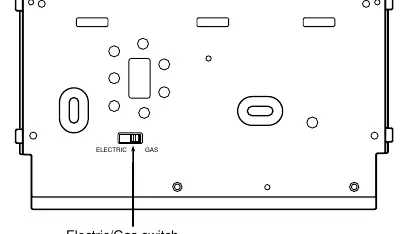
- Electric/Gas Switch: Locate the switch on the back of the thermostat base. Set to "ELECTRIC" if your system uses central electric heat or is a single-stage heat pump where the blower is energized by a separate circuit. Otherwise, keep it in the "GAS" position.
- Mounting: Remove the packing material. Pull the cover straight off the base. Use the base as a template to mark and drill mounting holes. Fasten the base to the wall using the provided screws.
- Wiring: Connect wires to the terminal screws on the base according to the specific wiring diagram for your system (see Figures 3 through 10 in the manual).
Battery Location
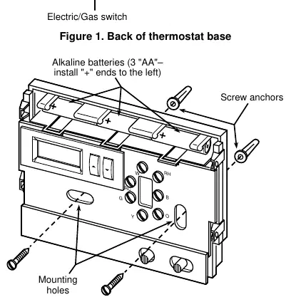
The thermostat requires 3 "AA" alkaline batteries. Batteries are pre-installed at the factory with a battery tag to prevent drainage. You must remove this tag to power the unit. If the display shows "BATTERY", replace the batteries with fresh "AA" Energizer alkaline batteries. Ensure the positive (+) ends are installed to the left.
Operation
The thermostat consists of a cover and a base. The control buttons are located behind the door on the bottom of the cover.
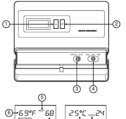
- Buttons: Use the red arrow to raise the temperature and the blue arrow to lower it.
- Switches: The FAN switch toggles between ON (continuous) and AUTO (cycles with system). The SYSTEM switch toggles between HEAT, OFF, and COOL.
- Temperature Adjustment: To change the temperature display between Fahrenheit and Celsius, press both arrow buttons simultaneously after power-up.
- System Testing: Use the FAN and SYSTEM switches to verify operation. Note that the cooling system has a built-in 5-minute delay to protect the compressor.
Specifications
- Electrical Rating: 8 to 30 VAC 50/60 Hz or D.C.
- Max Load: 1.5 Amps per terminal (1.5 Amps total).
- Setpoint Range: 45°F to 90°F (7°C to 32°C).
- Operating Humidity: 0 to 90% RH (non-condensing).
Practical help
Common problems
Display is blank except for the word 'BATTERY'
The batteries are low. Replace with 3 fresh 'AA' alkaline batteries.
Cooling system does not start immediately
The thermostat has a 5-minute compressor protection delay. Wait 5 minutes for the system to engage.
Thermostat not controlling system correctly
Verify the electric/gas switch on the back of the base is set correctly for your system type.
Before use
- Disconnect power at the main fuse box.
- Identify and label all wires from the old thermostat.
- Remove the battery tag to engage power.
- Set the electric/gas switch on the back of the base.
- Ensure the outdoor temperature is above 50°F before testing the cooling system.
Specs in practice
- Electrical Rating
- Compatible with 8-30 VAC/DC systems.
- Compressor Delay
- A 5-minute safety delay prevents the compressor from short-cycling.
- Setpoint Range
- The temperature can be set between 45°F and 90°F.
Images and diagrams
- Figure 1: Shows the location of the Electric/Gas switch on the back of the thermostat base.
- Figure 2: Illustrates battery installation and mounting hole locations.
- Figures 3-10: Provide specific wiring schematics for various heating and cooling system configurations.
Model compatibility
- Do not use with multi-stage systems.
- Do not use with systems exceeding 30 VAC and 1.5 amps.
- Do not use with 3-wire zoned hydronic heating systems.

Manual page author
Michael Turner
Technical manual editor
Reviews PDF manuals for structure, safety notes, and practical product details so readers can find the right information quickly.