HVAC / Thermostats & Controls
Installation Instructions for White-Rodgers 1F90-71 Thermostat
A comprehensive installation and configuration guide for the White-Rodgers 1F90-71 5-Day/2-Day Electronic Digital Thermostat. Includes wiring diagrams, system configuration, and setup steps.
Quick answers from the manual
Quick answer
- The 1F90-71 is a 5-day/2-day programmable thermostat. Installation requires mounting the subbase, connecting wires according to the specific system diagram (Figures 4-11), and configuring the Group A and B switches on the back of the unit. p. 1, 2, 3, 4
Key actions
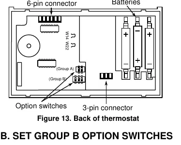
- Set option switches before mounting p. 6
- Clip wire W14 for electric heat systems p. 7
First start
- Install batteries and program before mounting p. 2, 6
Problems and fixes
Compressor lockout
Wait 5 minutes for the built-in delay to expire.
p. 7, 8Maintenance and reset
- Remove batteries for 2 minutes when changing Group B switches p. 6
Technical specifications
| Parameter | Value | Meaning | Pages |
|---|---|---|---|
| Electrical Rating | 17-30 VAC, 50/60 Hz | Operating voltage range | p. 2 |
| Max Load | 1.5 Amps | Maximum total load for all terminals combined | p. 2 |
Where to find it in the PDF
- Installation Instructions p. 1, 2, 3, 4
- Operation and Configuration p. 6, 7, 8
Table of contents
Manual images
Click an image to enlargeImportant Information
The White-Rodgers 1F90-71 is a wall-mounted, low voltage thermostat designed for 5-day/2-day programming. It requires three AA batteries to maintain programs during power failures. Warning: Do not use on circuits exceeding 30 VAC or 1.5 Amps. This device is not compatible with multi-stage or heat pump systems.
Installation
New Installation
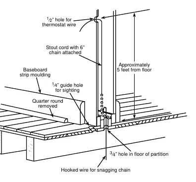
- Select a location about 5 feet above the floor on an interior partitioning wall.
- Avoid direct sunlight, lamps, fireplaces, or areas with poor air circulation.
- Drill a 1/2 inch hole for the thermostat wire and route the wire to the location.
- Program the thermostat with batteries installed before attaching it to the subbase.
Replacement Installation
- Shut off electricity at the main fuse box and verify power is off with a voltmeter.
- Identify existing wires using the provided labels and Table 1 in the manual before disconnecting.
- Pull at least six inches of wire out of the wall to prevent it from falling back.
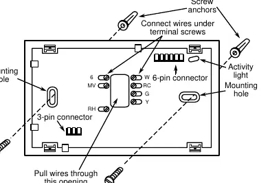
- Attach the subbase to the wall using the mounting screws.
Wiring Diagrams
The manual provides specific wiring diagrams for various system types, including:
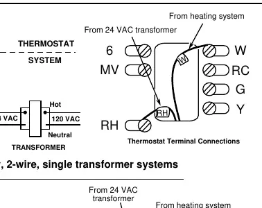
- Heat only (2-wire and 3-wire)
- Cool only (3-wire)
- Heat/Cool (4-wire and 5-wire)
- Millivolt systems
- Zone valve systems
Note: If you have a central electric heat system where the blower is energized by a separate circuit, you must clip wire W14 on the back of the thermostat.
System Configuration
The thermostat features Group A and Group B option switches located on the back of the unit. Important: Any time Group B switches are changed, batteries must be removed for a minimum of two minutes. Group A switches control keypad activity, lockout, and temperature range limits. Group B switches control automatic/manual changeover and heating/cooling system types.
Operation and Testing
The thermostat includes a built-in 5-minute compressor short-term cycle protection delay. If the compressor does not start immediately, wait for this delay to expire. To test the system, use the System Switch to select HEAT or COOL and adjust the temperature setpoint. If the fan does not operate, ensure the red jumper wire is properly installed between the RH and RC terminals.
Practical help
Common problems
Fan does not operate
Ensure the red jumper wire is properly installed between the RH and RC terminals. Check that the system is a type compatible with the G terminal.
Compressor will not start
The thermostat has a 5-minute short-term cycle protection delay. Wait for the delay to expire or use the Lockout Bypass Option (for technicians only) during testing.
Display is blank or program lost
Check the three AA batteries. They are required to maintain the program during power failures.
Before use
- Disconnect electrical power at the main fuse box.
- Verify power is off using a voltmeter.
- Set option switches to the desired position before mounting.
- Install batteries and program the thermostat before attaching to the subbase.
- Ensure the wall is an interior partitioning wall, not an outside wall.
Specs in practice
- Electrical Rating
- 17 to 30 VAC, 50/60 Hz. Maximum total load 1.5 Amps.
- Setpoint Temperature Range
- 40°F to 99°F (4°C to 37°C).
- Operating Ambient Temperature
- 32°F to 105°F.
Images and diagrams
- Figure 1: Guide for routing thermostat wires through the wall.
- Figure 3: Subbase terminal layout showing where to connect wires.
- Figures 4-11: Specific wiring schematics for different HVAC system configurations.
Model compatibility
- Not for use with multi-stage systems.
- Not for use with heat pump systems.
- Not for use with systems exceeding 30 VAC and 1.5 Amps.

Manual page author
Michael Turner
Technical manual editor
Reviews PDF manuals for structure, safety notes, and practical product details so readers can find the right information quickly.