HVAC / Thermostats & Controls
Installation and Operating Instructions for White-Rodgers Blue Universal Thermostat
Comprehensive installation and operating guide for the White-Rodgers Blue Universal Thermostat. Includes wiring diagrams, configuration menu settings, programming instructions, and troubleshooting steps for models 1F85CA-0471, 1F85-0471...
Quick answers from the manual
Quick answer
- This manual provides installation, wiring, configuration, and programming instructions for the White-Rodgers Blue Universal Thermostat (models 1F85CA-0471, 1F85-0471, 1F83-0471). p. 1
Key actions
- Access Installer Menu p. 5
- Reset Thermostat p. 9
First start
- Install 2 AA batteries, mount the base, connect wires according to the diagram, and configure settings via the Installer Menu. p. 2, 5
Problems and fixes
No Heat/No Cool
Check fuse, power switch, and wiring connections.
p. 9
Comfort Alert Codes
Refer to the table on page 10 for specific flash codes (e.g., 1 Flash = Long run time).
p. 10Error codes
| Code | Meaning | Action | Pages |
|---|---|---|---|
| 1 Flash | Long run time | Check system | p. 10 |
| 2 Flashes | System pressure trip | Check system | p. 10 |
| 3 Flashes | Short cycling | Check system | p. 10 |
| 4 Flashes | Locked rotor | Check system | p. 10 |
| 5 Flashes | Open circuit | Check system | p. 10 |
| 6 Flashes | Open start circuit | Check system | p. 10 |
| 7 Flashes | Open run circuit | Check system | p. 10 |
| 8 Flashes | Welded Contactor | Check system | p. 10 |
Maintenance and reset
- Reset programming, clock and configuration settings by pressing the up arrow, down arrow, and FAN button simultaneously. p. 9
Technical specifications
| Parameter | Value | Meaning | Pages |
|---|---|---|---|
| Setpoint Range | 45° to 90°F (7° to 32°C) | Temperature control range | p. 1 |
| Electrical Rating | mV to 30 VAC, NEC Class II, 50/60 Hz or DC | Power requirements | p. 1 |
Where to find it in the PDF
- Specifications p. 1
- Installation p. 2
- Wiring Diagrams p. 3
- Installer Configuration Menu p. 5, 6
- Troubleshooting p. 9, 10
Table of contents
Manual images
Click an image to enlargeQuick Guide
This manual provides instructions for the White-Rodgers Blue Universal Thermostat. Before installation, ensure power is disconnected at the main fuse or circuit breaker. The thermostat is compatible with various systems, including Heat Pump, Gas, Oil, Electric, and Hydronic systems. Configuration is performed via the Installer Menu, accessed by holding the Menu button for 5 seconds.
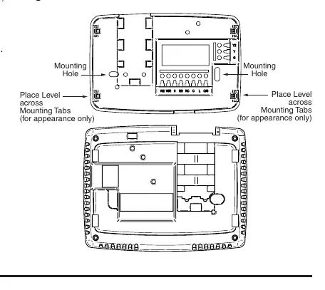
Installation
To install the thermostat: 1. Remove the old thermostat cover and base, labeling wires before disconnecting. 2. Mount the new base using the provided holes. 3. Connect wires to the terminal block according to the wiring diagrams. 4. Install 2 AA alkaline batteries. 5. Snap the thermostat body onto the base.
Wiring Connections
Refer to the wiring diagrams on page 3 for specific system configurations. Ensure the correct terminal designations are used (e.g., L, O, B, Y, Y2, W/E, W2, G, RH, RC, C, 6). If your system does not provide an E connection, jumper W2 to W/E for Emergency Mode.
Installer Configuration Menu
To access the menu, ensure the thermostat is in Heat, Cool, or Auto mode, then press the Menu button for at least 5 seconds. Use the Menu button to advance through items and the arrow buttons to change options. Settings include system type (Multi-Stage, Heat Pump, Single Stage), Cool Savings, Energy Management Recovery, and cycle rates.
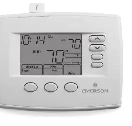
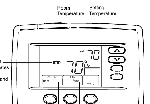
Operating Your Thermostat
Choose the Fan setting (Auto or On) and System setting (Heat, Off, Cool, Auto, Emer). For programmable models, you can set heating and cooling schedules. Manual operation is possible by using the Hold feature to override the program.
Troubleshooting
If the thermostat malfunctions, try resetting it by removing batteries and wires from R and C terminals for 2 minutes, or by pressing the up arrow, down arrow, and FAN button simultaneously. Refer to the Comfort Alert Codes on page 10 if the thermostat displays 'Call For Service'.
Practical help
Common problems
No Heat/No Cool/No Fan
Check for a blown fuse or tripped circuit breaker, ensure the furnace power switch is ON, verify the blower compartment door is secure, and check for loose wiring connections.
Thermostat Setting & Thermometer Disagree
The thermometer can be adjusted +/- 4 degrees. Use the Temperature Display Adjustment in the Configuration Menu.
Furnace Cycles Too Fast or Too Slow
Adjust the cycle rate (SL/ME/FA) in the Configuration Menu (step 6 for heat, 7 for cool, or 8 for heat pump).
Before use
- Disconnect power at the main fuse or circuit breaker before installation.
- Label all wires from the old thermostat before disconnecting.
- Ensure system compatibility (Heat Pump, Gas, Oil, Electric, etc.).
- Install 2 AA alkaline batteries.
- Verify wiring connections against the provided diagrams.
Specs in practice
- Setpoint Range
- 45° to 90°F (7° to 32°C)
- Terminal Load
- 1.5 A per terminal, 2.5A maximum for all terminals combined.
- Operating Ambient
- 32° to +105°F (0° to +41°C)
Images and diagrams
- Wiring diagrams show connections for Heat Pump, Single Stage, and Multi-Stage systems.
- Battery door is located on the front of the unit.
Model compatibility
- Compatible with Heat Pump, Gas, Oil, Electric, and Hydronic systems.
- 1F85CA-0471 supports Comfort Alert II Module.

Manual page author
Emily Carter
User documentation editor
Prepares concise manual descriptions and highlights the most useful setup, operation, and maintenance information for readers.