HVAC / Thermostats & Controls
Installation and Operating Instructions for White-Rodgers 1F86-0471 Thermostat
Quick guide for the White-Rodgers 1F86-0471 thermostat. Includes installation steps, wiring, configuration menu, programming, and troubleshooting.
Quick answers from the manual
Quick answer
- The White-Rodgers 1F86-0471 is a single-stage thermostat for heating and cooling systems. It supports battery or hardwired power and features an installer configuration menu for system settings. p. 1
Key actions
- Access Installer Configuration Menu p. 4
- Reset Thermostat p. 8
First start
- Install batteries p. 2
- Set SS/HP switch p. 2
Problems and fixes
No Heat/No Cool
Check fuse, power switch, blower door, and wiring.
p. 8Maintenance and reset
- Reset programming, clock, and configuration settings p. 8
Technical specifications
| Parameter | Value | Meaning | Pages |
|---|---|---|---|
| Electrical Rating | mV to 30 VAC | Power requirements | p. 1 |
Where to find it in the PDF
- Installation p. 2
- Installer Configuration Menu p. 4
- Programming p. 6
- Troubleshooting p. 8
Table of contents
Manual images
Click an image to enlargeImportant Information from the Manual
The White-Rodgers 1F86-0471 is a single-stage thermostat designed for heating and cooling systems, including gas, oil, electric, and single-stage heat pumps. This document provides instructions for installation, configuration, and operation. Always disconnect power at the main fuse or circuit breaker before beginning installation to prevent electrical shock or equipment damage.
Installation
Removing the Old Thermostat:
- Label each wire with the terminal designation before disconnecting.
- Disconnect wires one at a time and prevent them from falling back into the wall.
- Remove the old base by loosening all captive screws.
Installing the New Thermostat:
- Pull the thermostat body off the base.
- Place the base over the wall hole, mark mounting locations, and drill holes. Use plastic anchors if necessary.
- Fasten the base to the wall using the provided mounting holes.
- Connect wires to the terminal block on the base.
- Push excess wire into the wall and plug the hole with fire-resistant material to prevent drafts.
- Snap the thermostat onto the base.
Configuration Switches
Before operation, ensure the internal switches are set correctly:
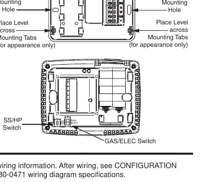
- SS/HP Switch: Set to 'SS' for conventional single-stage systems or 'HP' for single-stage heat pump systems.
- GAS/ELEC Switch: Set to 'GAS' for gas/oil systems (thermostat does not power fan on call for heat) or 'ELEC' for electric systems (thermostat powers fan on call for heat).
Installer Configuration Menu
To access the installer configuration menu, ensure the thermostat is in Heat, Cool, or Auto mode, then press the Menu button for at least 5 seconds. Use the Menu button to advance through items and the arrow buttons to change options.
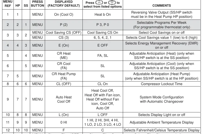
- Reversing Valve Output: Configures the O/B terminal for heat pump applications.
- Cool Savings: An optional energy-saving feature that adjusts the setpoint during high-demand cooling periods.
- Energy Management Recovery (EMR): Allows the thermostat to start heating or cooling early to reach the setpoint at the scheduled time.
- Compressor Lockout: Prevents short cycling by waiting 5 minutes between cooling cycles.
- Temperature Display Adjustment: Allows calibration of the room temperature display by +/- 4 degrees.
Operation
Fan Settings:
- Auto: Runs the fan only when the heating or cooling system is active.
- On: Runs the fan continuously for air circulation or cleaning.
System Settings:
- Heat: Controls heating only.
- Cool: Controls cooling only.
- Auto: Automatically switches between heating and cooling based on indoor temperature.
- Off: Turns off both heating and cooling systems.
Programming
For programmable models, you can set heating and cooling schedules. The thermostat comes with factory-set energy-saving programs. To customize, use the Menu and Schedule buttons to set times and temperatures for different periods (Wake Up, Leave For Work, Return Home, Go To Bed).
Troubleshooting
If the thermostat experiences issues, such as a blank display or erratic operation, perform a reset:
- Remove the wires from terminals R and C (do not short them together).
- Remove the batteries for 2 minutes.
- Replace the wires and batteries.
If the system does not heat or cool, check the fuse/circuit breaker, furnace power switch, and ensure the blower compartment door is properly installed.
Practical help
Common problems
No Heat/No Cool/No Fan
Check for a blown fuse or tripped circuit breaker, ensure the furnace power switch is ON, verify the blower compartment door is properly installed, and check for loose wiring connections.
Thermostat display blank or erratic
Perform a reset by removing wires from terminals R and C and removing batteries for 2 minutes.
System runs constantly
Check for shorted wiring, ensure the fan switch is not set to ON, or test the system operation.
Before use
- Verify system compatibility (Gas, Oil, Electric, or Heat Pump).
- Label all wires before disconnecting the old thermostat.
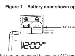
- Install 2 AA alkaline batteries.
- Set the SS/HP switch to the correct position (SS or HP).
- Set the GAS/ELEC switch to the correct position (GAS or ELEC).
Specs in practice
- Electrical Rating
- mV to 30 VAC, NEC Class II, 50/60 Hz or DC.
- Terminal Load
- 1.0 A per terminal, 1.5A maximum for all terminals combined.
- Setpoint Range
- 45° to 90°F (7° to 32°C).
- Operating Humidity
- 90% non-condensing maximum.
Images and diagrams
- Figure 1: Battery door location and installation.
- Figure 2: Base and rear view showing mounting holes and configuration switches.
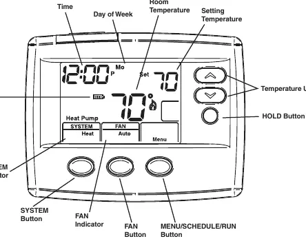
- Figure 4: Home screen display elements.
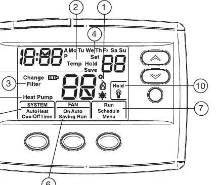
- Figure 5: Programming and configuration icons.
Model compatibility
- Compatible with Gas, Oil, Electric, and single-stage Heat Pump systems.
- Not compatible with systems with up to 3 stages heat/2 stages cool.
- Not compatible with Heat Pump systems with Aux or Emergency Heat.

Manual page author
Michael Turner
Technical manual editor
Reviews PDF manuals for structure, safety notes, and practical product details so readers can find the right information quickly.