Tools / Hose Reels
Operation Manual for XPOtool 2-in-1 Brush Cutter 61495/61496
Quick guide for the XPOtool 2-in-1 Brush Cutter (models 61495, 61496). Includes assembly instructions, safety precautions, fuel mixing ratios, operation steps, and maintenance procedures.
Quick answers from the manual
Quick answer
- The XPOtool 2-in-1 Brush Cutter requires a 25:1 gasoline-to-oil mixture. Always wear protective gear and maintain a 15m safety perimeter. p. 3, 6, 11
Key actions
- Sharpen blade and grease gear case every 25 hours of use. p. 14, 15
First start
- Open fuel cock, close choke, set throttle to start, and pull starter rope. p. 11, 12
Problems and fixes
Blade rotates at idle
Adjust the idle screw on the carburetor.
p. 15Maintenance and reset
- Sharpen blade and grease gear case every 25 hours. p. 14, 15
Technical specifications
| Parameter | Value | Meaning | Pages |
|---|---|---|---|
| Fuel Mix | 25:1 | Gasoline to 2-cycle oil ratio | p. 11 |
| Spark Plug Gap | 0.6-0.7 mm | Distance between electrodes | p. 14 |
Where to find it in the PDF
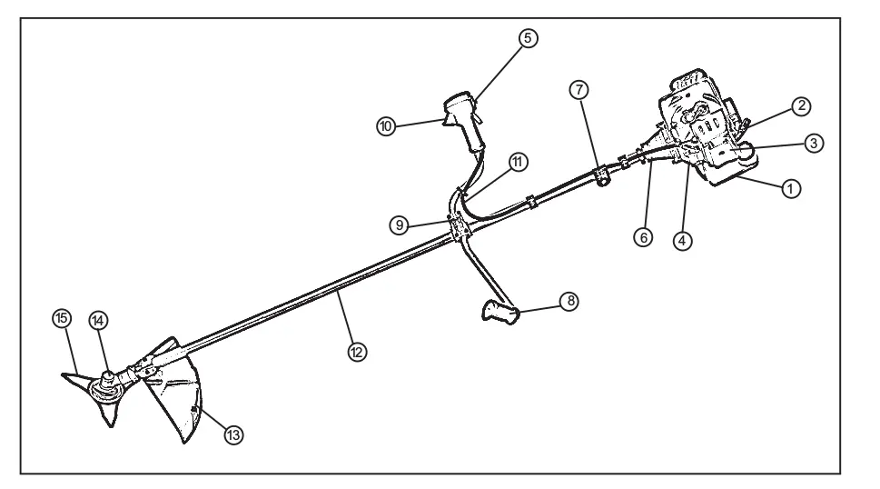
- Parts List p. 4
- Assembly p. 8, 9, 10
- Maintenance p. 14, 15
Table of contents
Manual images
Click an image to enlargeQuick guide from the manual
This manual provides essential instructions for the safe operation and maintenance of the XPOtool 2-in-1 Brush Cutter. Key requirements include using a 25:1 gasoline-to-oil fuel mixture, wearing appropriate protective gear, and maintaining a 15-meter safety perimeter during operation.
Safety Precautions
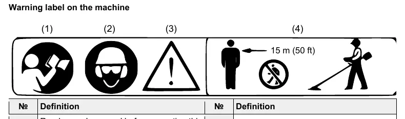
- Protective Gear: Always wear a helmet, protection goggles or face protector, thick work gloves, and non-slip work boots.
- Fuel Handling: Use a 25:1 gasoline-to-oil mixture. Refuel only when the engine is off and cool, away from any heat sources or open flames.
- Environment: Maintain a 15-meter safety perimeter around the operator. Do not operate in poor visibility, on slippery ground, or during severe weather.
- Prohibitions: Never modify the brush cutter. Do not operate indoors due to carbon monoxide risks.
Assembly
Engine and Main Pipe
Align the hanger and the fuel tank, then secure the connection using the 4 provided socket screws with equal force.
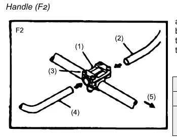
Handle and Controls
Loosen the 4 bolts on the handle bracket, insert the left and right handle assemblies, and re-tighten the bolts securely. Ensure the throttle cable is correctly hooked into the throttle lever hole.
Cutting Attachments
- Safety Guard: Attach to the gear case using the clamp and 2 M5x25 bolts.
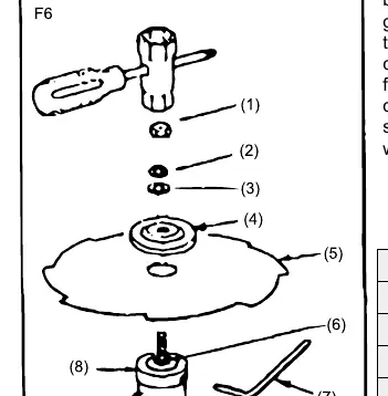
- Metal Blade: Set the inner holder to the gear shaft, place the blade, then the outer holder, and secure with the bolt, spring washer, and washer.
- Nylon Cutter: Secure the inner holder with the L-shaped bar and tighten the nylon cutter manually onto the bolt.
Operation
Starting the Engine
- Ensure the unit is free of fuel leaks and loose fittings.
- Tighten the fuel tank cap.
- Open the fuel tank cock and move the choke lever to the closed position.
- Set the throttle lever to the starting position.
- Pull the starter rope quickly.
- Once started, gradually open the choke and allow the engine to warm up for 2-3 minutes.
Stopping the Engine
Return the throttle lever to the idling position and push the engine switch button.
Maintenance
- Blade: Sharpen cutting edges every 25 hours of service. Ensure the bottom corner is rounded.
- Air Filter: Clean in warm soapy water if required. Replace if broken or shrunk.
- Spark Plug: Inspect and clean electrodes. Adjust the gap to 0.6–0.7 mm.
- Gear Case: Supply multi-purpose grease every 25 hours of use.
- Carburetor: Use the idle adjustment screw to adjust engine rotation at the lowest speed position.
Practical help
Common problems
Engine fails to start
Check fuel level, ensure fuel cock is open, verify choke position, and check spark plug condition.
Blade continues to rotate after throttle release
Check throttle wire tension and adjust the idle screw on the carburetor.
Poor engine performance/acceleration
Clean or replace the air filter and fuel filter; check for carbon build-up in the muffler.
Before use
- Check for loose screws or bolts
- Inspect fuel lines for leaks
- Ensure blade is sharp and undamaged
- Wear protective gear (helmet, goggles, gloves, boots)
- Clear 15m perimeter of obstacles
Specs in practice
- Fuel Mix Ratio
- 25:1 (Gasoline to 2-cycle oil)
- Spark Plug Gap
- 0.6-0.7 mm
- Maintenance Interval
- Grease gear case and sharpen blade every 25 hours
Images and diagrams
- Explosion view shows assembly of engine, handle, and cutting head
- F6 shows blade installation sequence
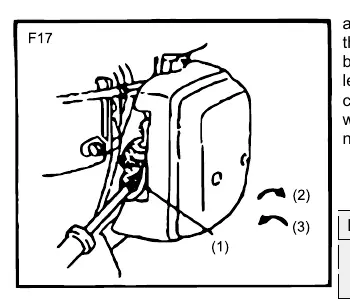
- F17 shows idle adjustment screw location
Model compatibility
- Designed for cutting grass and shrubs only
- Use only certified replacement parts

Manual page author
Michael Turner
Technical manual editor
Reviews PDF manuals for structure, safety notes, and practical product details so readers can find the right information quickly.