Hvac / Air Conditioners
Installation and Owner's Manual for ACIQ 18K-55K Multi-Zone Condenser
Comprehensive installation and operation guide for ACIQ 18K-55K Standard & Extreme Heat Multi-Zone Condensers. Includes safety precautions, wiring diagrams, piping installation, and troubleshooting.
Table of contents
Manual images
Jump to the sectionQuick guide from the manual
This document provides essential installation and operational instructions for the ACIQ 18K-55K series multi-zone condenser units. It covers safety protocols, refrigerant piping, electrical wiring, and system testing. Installation must be performed by qualified personnel in accordance with local and national regulations.
Safety Precautions
Improper installation can lead to serious injury or property damage. Key safety requirements include:
- Ensure the unit is properly grounded.
- Use only specified wires and components.
- Do not install near combustible gas leaks or in areas exposed to heavy dust or salty air.
- If using flammable refrigerants, ensure the area is well-ventilated and free of ignition sources.
- A leak detection system is installed; if triggered, the unit will display an error code and stop the compressor.
Product Overview
The system consists of an outdoor condenser unit connected to multiple indoor units (wall-mounted, duct/ceiling, floor console, or cassette types). The outdoor unit features a fan, stop valves, and connection ports for refrigerant piping and electrical cables.
Installation
The installation process involves:

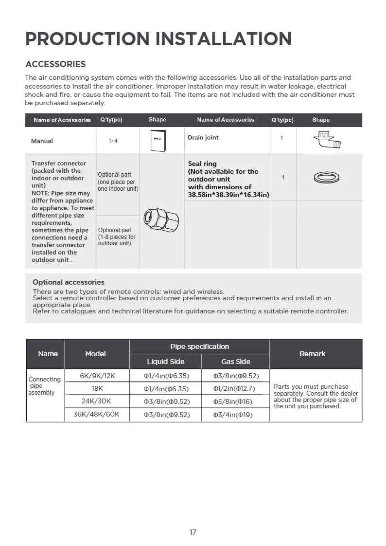
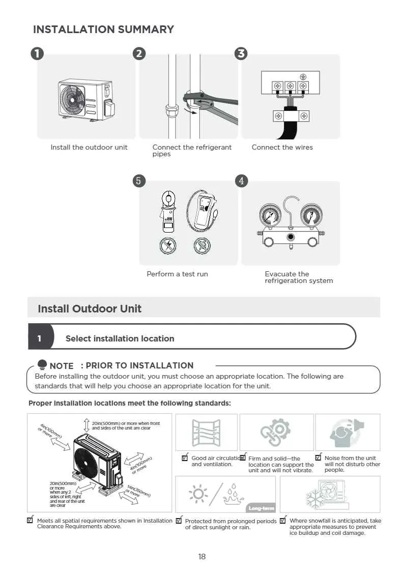
- Selecting an appropriate location with good air circulation and structural support.
- Installing the outdoor unit and securing it with anchors.
- Installing the drain joint (for heat pump units).
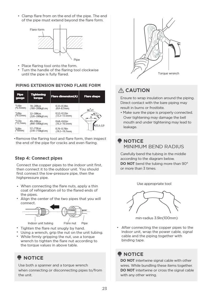
- Connecting refrigerant piping, ensuring proper flaring and insulation.
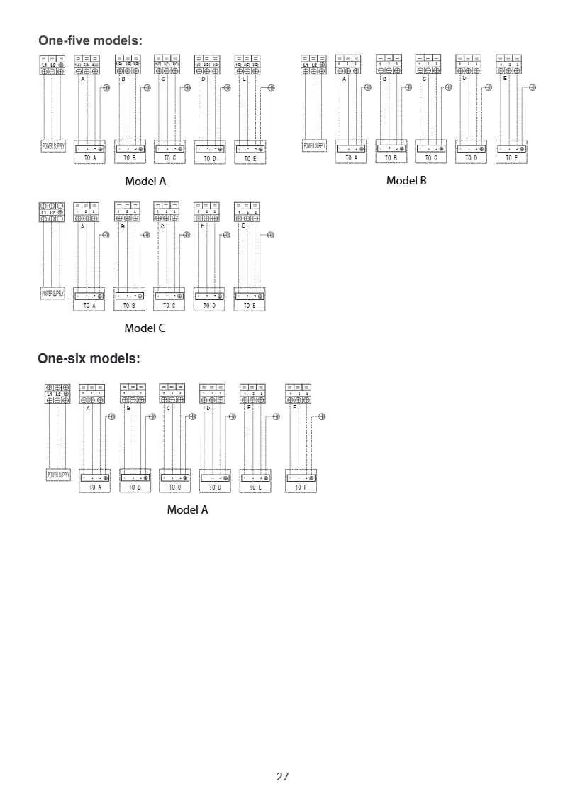
- Performing electrical wiring according to the provided diagrams.
- Evacuating the refrigeration system using a vacuum pump.
- Performing a test run to verify system operation.
Operation and Maintenance
The system includes features like compressor protection (3-minute delay) and auto-restart. For optimal performance, keep doors and windows closed during operation and clean air filters every two weeks. If the unit will be idle for a long time, clean the unit, select FAN ONLY mode to dry the interior, and disconnect the power supply.
Troubleshooting
If the unit malfunctions, check the following before contacting a service provider:
- Unit does not turn on: Check power supply, fuses, and the 3-minute protection delay.
- Poor cooling/heating: Check for blocked air inlets/outlets, dirty filters, or open doors/windows.
- White mist/noises: Often normal due to temperature differences or refrigerant flow during defrosting.
Manufacturer information
ACiQ
Practical help
Common problems
Unit does not turn on
Check power supply, replace blown fuses, or wait 3 minutes for the protection feature to reset.
Poor cooling or heating performance
Clean dirty air filters, remove obstructions from air inlets/outlets, and ensure all doors and windows are closed.
Unit emits white mist
This is often normal in humid conditions or during the defrosting process.
Before use
- Ensure indoor and outdoor units are properly installed.
- Verify all piping and wiring connections are secure.
- Confirm the refrigeration system has been evacuated and leak-tested.
- Check that the power voltage matches the unit's rating.
- Ensure the drainage system is clear and unobstructed.
Specs in practice
- Compressor start/stop frequency
- Minimum 3 minutes between cycles to prevent overloading.
- Voltage fluctuation
- Must be within ±10% of the rated voltage.
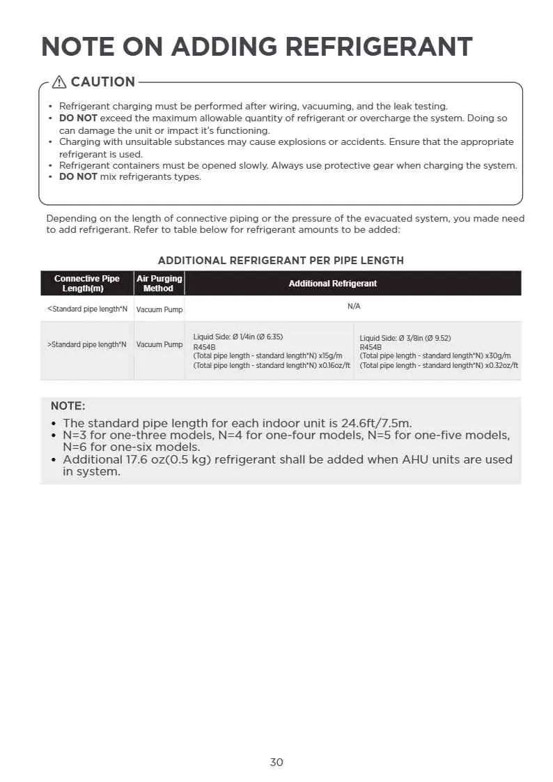
- Standard pipe length
- 24.6ft (7.5m) per indoor unit; additional refrigerant is required if exceeded.
Images and diagrams
- Installation diagram shows clearance requirements (min 12cm/30cm) around indoor and outdoor units.
- Wiring figures illustrate correct terminal connections between outdoor and indoor units.
- Automatic wiring/piping correction function uses a check switch on the PCB to verify connections.
Model compatibility
- 24K/30K/36K indoor units can only be connected with an A system.
- If two 24K/30K/36K indoor units are used, they can be connected with A and B systems.
- Only blast-proof ceramic fuses are permitted for PCB protection.

Manual page author
Emily Carter
User documentation editor
Prepares concise manual descriptions and highlights the most useful setup, operation, and maintenance information for readers.