Industrial / I/O Modules
Installation Instructions for Allen-Bradley 1734-FPD POINT I/O Field Potential Distributor Module
Comprehensive installation and wiring guide for the Allen-Bradley 1734-FPD and 1734-FPDK Field Potential Distributor Modules. Includes mounting instructions, wiring diagrams for 12/24V DC and 120/240V AC, and technical specifications.
Quick answers from the manual
Quick answer
- The 1734-FPD module is used to break field power distribution in a POINT I/O system, allowing for logical or functional partitioning of I/O modules. p. 4
Key actions
- Install on DIN rail p. 5
- Wire the module p. 6, 7
Problems and fixes
Electric arc during connection
Ensure power is removed or the area is nonhazardous before connecting or disconnecting wiring.
p. 6Maintenance and reset
- Cleaning p. 4
Technical specifications
| Parameter | Value | Meaning | Pages |
|---|---|---|---|
| Input voltage | 12V DC, 24V DC, 120V AC, 240V AC | Nominal input voltage ratings | p. 7 |
| Max current | 10 A | Maximum input current | p. 7 |
Where to find it in the PDF
- Installation p. 5
- Specifications p. 7, 8
Table of contents
Manual images
Click an image to enlargeQuick guide from the manual
The 1734-FPD and 1734-FPDK Field Potential Distributor Modules are designed to break field power distribution within a POINT I/O system. This allows for logical or functional partitioning of I/O modules. The module is intended for use in Pollution Degree 2 industrial environments and must be mounted within a suitable enclosure.
Installation
The module is designed for DIN rail mounting. Ensure the DIN rail is zinc-plated chromate-passivated steel to ensure proper grounding. To install:

- Position the module vertically above the DIN rail.
- Engage the interlocking pieces with the unit on the left.
- Press down firmly to install the module on the DIN rail until the locking mechanism snaps into place.
Removal
To remove the module, you must first remove any I/O module installed in the base to the right:
- Pull up on the RTB (Removable Terminal Block) removal handle to remove the terminal block.
- Use a small-bladed screwdriver to rotate the DIN rail locking screw to a vertical position to release the locking mechanism.
- Lift the module straight up to remove.
Wiring
The module supports both 12/24V DC and 120/240V AC applications. Ensure power is removed or the area is nonhazardous before connecting or disconnecting wiring to avoid electric arcs.
12/24V DC Wiring
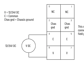
- Terminal 2: Chassis Ground
- Terminal 4: Common
- Terminal 6: +V DC
120/240V AC Wiring
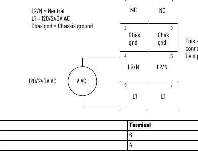
- Terminal 2: Chassis Ground
- Terminal 4: L2/N (Neutral)
- Terminal 6: L1 (120/240V AC)
Safety and Maintenance
This equipment is sensitive to electrostatic discharge (ESD). Always touch a grounded object before handling and use a static-safe workstation if available. Do not attempt to repair the module; return it to the manufacturer if damaged. Use only a soft, dry anti-static cloth for cleaning; do not use cleaning agents.
Manufacturer information
Allen-Bradley
Practical help
Common problems
Improper or intermittent grounding
Ensure the DIN rail is zinc-plated chromate-passivated steel and secured to the mounting surface approximately every 200 mm.
Electric arc during installation or removal
Ensure power is removed or the area is nonhazardous before connecting or disconnecting the module or wiring.
Before use
- Verify the environment is Pollution Degree 2
- Ensure DIN rail is properly grounded
- Check that power is removed before installation
- Use appropriate static-safe handling procedures
- Ensure the enclosure is designed for the specific environmental conditions
Specs in practice
- Input voltage
- Supports 12V/24V DC and 120V/240V AC nominal inputs.
- Input current, max
- Maximum current capacity is 10 A.
Images and diagrams
- Wiring diagrams for 12/24V DC and 120/240V AC are provided to show terminal connections for supply, common, and chassis ground.
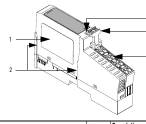
- Component diagram identifies the module label, interlocking side pieces, DIN rail locking screw, and terminal block handle.
Model compatibility
- Compatible with POINT I/O backplanes.
- Not intended for residential environments.
- Requires UKEX/ATEX/IECEx certified Rockwell Automation backplanes.

Manual page author
Michael Turner
Technical manual editor
Reviews PDF manuals for structure, safety notes, and practical product details so readers can find the right information quickly.