Industrial / Communication Modules
Installation Instructions for Allen-Bradley 1734-ACNR POINT I/O ControlNet Adapter
A comprehensive installation and configuration guide for the Allen-Bradley 1734-ACNR and 1734-ACRNK ControlNet Adapter. Includes step-by-step mounting instructions, wiring diagrams, status indicator troubleshooting, and technical...
Quick answers from the manual
Quick answer
- The 1734-ACNR is a communication interface for POINT I/O modules on a ControlNet network. Installation requires mounting on a DIN rail, setting the node address (01-99), and connecting 24V DC power. p. 5, 6, 7
Key actions
- Set the node address p. 6
- Mount the adapter p. 6
First start
- Configure autobaud p. 5
Problems and fixes
Module status flashing red
Recoverable fault: Firmware update, MAC ID changed, or CPU load exceeded.
p. 8Maintenance and reset
- Use a soft dry anti-static cloth to wipe down equipment. Do not use any cleaning agents. p. 4
Technical specifications
| Parameter | Value | Meaning | Pages |
|---|---|---|---|
| Input voltage | 10-28.8V DC | Nominal 24V DC input range. | p. 9 |
Where to find it in the PDF
- Installation p. 6
- Status Indicators p. 8
Table of contents
Manual images
Click an image to enlargeQuick Guide from the Manual
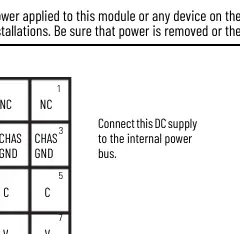
The 1734-ACNR and 1734-ACRNK are communication interfaces for POINT I/O modules on a ControlNet network. This document provides essential procedures for installation, wiring, and troubleshooting. Important: This equipment is intended for use in Pollution Degree 2 industrial environments and must be mounted within an enclosure. Always ensure power is removed or the area is nonhazardous before performing installation or maintenance to prevent electric arcs.
Installation
The adapter is designed for DIN rail mounting. Follow these steps to install:
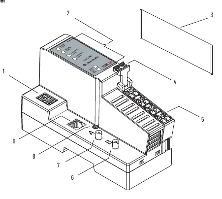

- Position the adapter vertically above the DIN rail.
- Press down firmly until the locking mechanism snaps into place.
- Set the node address using the 2-position thumbwheel switch (valid range 01-99).
- Remove the safety end cap by sliding it up to expose backplane and power interconnections.
- If replacing an existing adapter, disconnect the ControlNet connector, remove the RTB, and use a small screwdriver to release the DIN rail locking screw.
Wiring
Proper wiring is critical for system operation. Use zinc-plated chromate-passivated steel DIN rail to ensure proper grounding. Secure the DIN rail to the mounting surface approximately every 200 mm.
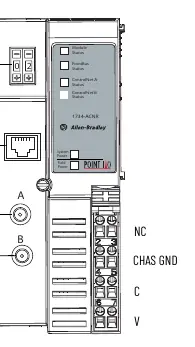
- Adapter Wiring: Connect the ControlNet cable using a tap; do not connect directly to the coax cable.
- Power Wiring: Connect 12/24V DC power to the internal power bus. Do not connect 120/240V AC power.
- NAP Port: The Network Access Port (NAP) is for temporary local programming only and requires a 1786-CP cable assembly.
Status Indicators
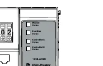
The adapter features several status LEDs to assist with troubleshooting:
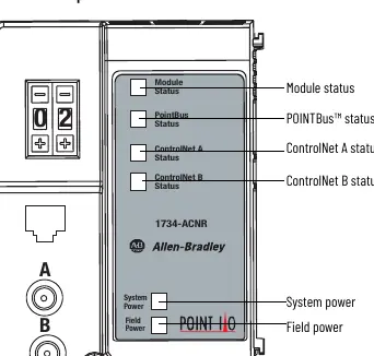
- Module Status: Steady green indicates normal operation. Flashing red indicates a recoverable fault (e.g., MAC ID changed, CPU load exceeded). Steady red indicates an unrecoverable fault (e.g., self-test failure).
- ControlNet A/B Status: Steady green indicates normal operation (MAC frames received). Flashing red/off indicates a severe link error.
- POINTBus Status: Green indicates the adapter is online with connections established.
Specifications
Key technical parameters for the 1734-ACNR adapter:
- Input Voltage: 10-28.8V DC (Nominal 24V DC).
- Operating Temperature: -20 to +55 °C (-4 to +131 °F).
- Expansion I/O Capacity: Up to 17 modules (dependent on backplane bus current draw).
- Dimensions: 76.2 x 54.9 x 133.4 mm.
Manufacturer information
Allen-Bradley
Practical help
Common problems
Module status LED is flashing red
A recoverable fault has occurred. Check for firmware updates, MAC ID changes, or excessive CPU load.
Improper grounding
Ensure you are using zinc-plated chromate-passivated steel DIN rail. Aluminum or plastic rails can result in intermittent grounding.
Electric arc during installation
Ensure power is removed or the area is confirmed nonhazardous before connecting or disconnecting any wiring or modules.
Before use
- Verify you are using Series C POINT I/O modules (Series A and B are not compatible).
- Ensure the DIN rail is zinc-plated steel and secured every 200 mm.
- Confirm the power supply is 24V DC (10-28.8V DC range).
- Set the node address thumbwheel to the desired address (01-99).
- Ensure the safety end cap is removed only when necessary and replaced to cover exposed interconnections.
Specs in practice
- Input Voltage
- Nominal 24V DC, with an operating range of 10-28.8V DC.
- Operating Temperature
- The device is rated for -20 to +55 °C (-4 to +131 °F).
- Expansion I/O Capacity
- Supports up to 17 modules, provided the total backplane current draw does not exceed 1.3 A.
Images and diagrams
- Figure 1: Identifies external features including the node address thumbwheel, status indicators, and terminal blocks.
- Figure 2: Shows the adapter wiring layout, including Coaxial channels A/B and terminal assignments.
- Figure 3: Illustrates the 12/24V DC power supply connection to the internal power bus.
Model compatibility
- Requires Series C POINT I/O modules.
- Not compatible with Series A or B POINT I/O modules.
- Intended for use in Pollution Degree 2 industrial environments.

Manual page author
David Miller
Documentation analyst
Organizes user manual content into clear summaries, with attention to model details, product context, and everyday usability.