Lighting / Fixtures
User Manual for American Lighting CTRL-WDMX-TRNRCV Wireless DMX512 Transceiver
Quick guide for the American Lighting CTRL-WDMX-TRNRCV Wireless DMX512 Transceiver. Learn about wiring, DIP switch configuration, transmission modes, and technical specifications.
Quick answers from the manual
Quick answer
- The CTRL-WDMX-TRNRCV is a 2.4G wireless DMX512 transceiver used to transmit DMX signals wirelessly between consoles and lighting fixtures. It requires a 5-24Vdc power supply and uses DIP switches for configuration. p. 1
Key actions
- Set device as Emitter or Receiver p. 2
- Adjust transmission power p. 2
- Connect DMX signal cable p. 3
First start
- Configure DIP switches for mode and ID, then connect 5-24Vdc power. p. 2
Technical specifications
| Parameter | Value | Meaning | Pages |
|---|---|---|---|
| Input Voltage | 5-24Vdc | Required power supply voltage | p. 1 |
| Communication Distance | 350m | Maximum range in open environment | p. 1 |
Where to find it in the PDF
- Technical Specifications p. 1
- DIP Switch Configuration p. 2
- Wiring Diagram p. 3
Table of contents
Manual images
Click an image to enlargeQuick guide from the manual
The American Lighting CTRL-WDMX-TRNRCV is a 2.4G wireless DMX512 transceiver designed to transmit DMX signals wirelessly between a DMX console and lighting fixtures. It supports point-to-point and multi-point communication, as well as relay functions to extend communication distance. The device requires a 5-24Vdc power supply.
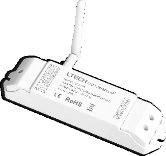
Technical Specifications
- Input Voltage: 5-24Vdc
- Working Frequency: 2.4GHz
- Communication Distance: 350m (in open environment)
- Working Temperature: -30°C to 55°C
- Max. Transmitted Power: 20dBm
- Receiver Sensitivity: -96dBm
- Weight: 125g
DIP Switch Configuration
The device uses DIP switches to configure its operation mode and transmission power.
- Mode Selection (Switches 9-10):
- Emitter: Set switch 10 to OFF, switch 9 to OFF.
- Receiver: Set switch 10 to ON, switch 9 to OFF.
- Self-testing mode: Set switch 10 to OFF, switch 9 to ON.
- Transmission Power (Switches 7-8): Adjusts signal strength. Refer to the table in the manual for specific dBm settings (High, Middle, Low).
- ID Settings (Switches 1-6): Used to match emitters and receivers. Ensure both units have the same ID settings for communication.
Wiring and Installation
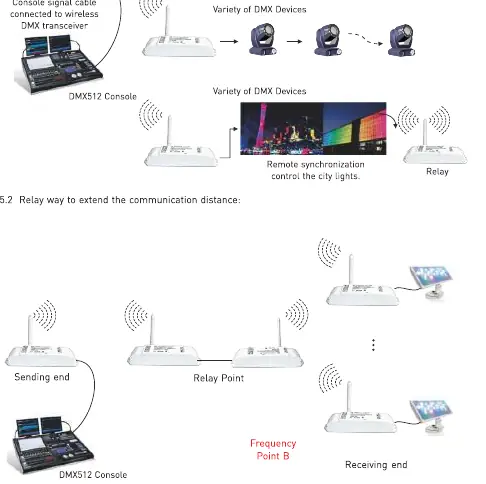
The transceiver connects to the DMX console via a DMX signal cable. For receiving ends, the transceiver connects to DMX devices. The system supports a relay configuration where multiple transceivers can be used to extend the signal range.
Safety and Maintenance
- The product is not waterproof; avoid exposure to sun and rain. If installed outdoors, use a waterproof enclosure.
- Ensure good ventilation to prolong the life of the controller.
- Verify that the output voltage of the LED power supply complies with the working voltage of the product.
- Ensure all wire connections and polarities are correct before applying power.
- If a fault occurs, return the product to the supplier; do not attempt to repair it yourself.
Manufacturer information
American Lighting Inc.
Practical help
Common problems
Signal not transmitting
Check DIP switch settings (9-10) to ensure one unit is set as Emitter and the other as Receiver.
Short communication range
Adjust the transmission power using DIP switches 7 and 8 to a higher setting.
Device not powering on
Verify that the power supply provides 5-24Vdc and that connections are secure.
Before use
- Verify input voltage is 5-24Vdc.
- Ensure the installation environment is dry (non-waterproof).
- Check that the unit has adequate ventilation.
- Set DIP switches 9-10 to define the device as Emitter or Receiver.
- Ensure Emitter and Receiver have matching ID settings (DIP 1-6).
Specs in practice
- Communication Distance
- Up to 350m in an open environment; actual distance may vary based on weather and environment.
- Working Temperature
- The device operates safely between -30°C and 55°C.
- Max. Transmitted Power
- 20dBm; adjustable via DIP switches to manage signal strength.
Images and diagrams
- DIP Switch 9-10: Determines if the unit acts as an Emitter or Receiver.
- DIP Switch 7-8: Controls transmission power levels.
- Wiring Diagram: Illustrates the connection path from the DMX console to the Emitter, and from the Receiver to DMX devices.
Model compatibility
- Compatible with standard DMX512 protocol.
- Supports point-to-point and multi-point communication.
- Relay function available for extending signal range.

Manual page author
Emily Carter
User documentation editor
Prepares concise manual descriptions and highlights the most useful setup, operation, and maintenance information for readers.