Lighting / Fixtures
Installation and User Guide for Ansell AFRLED/M3/ST Emergency Pack
Comprehensive installation and maintenance guide for the Ansell AFRLED/M3/ST Emergency Pack. Includes wiring instructions, self-test procedures, and battery maintenance details.
Quick answers from the manual
Quick answer
- The AFRLED/M3/ST is an emergency pack for specific Ansell LED downlights. It requires professional installation, specific wiring (Permanent/Switched Live), and performs automatic routine self-tests. p. 1, 2
Key actions
- Installation p. 1
First start
- When the unit is first installed, it will randomly select a test date between 200 and 365 days. p. 2
Problems and fixes
Continuous red LED
Battery failure or disconnection.
p. 2
Flashing red LED
Failed duration test.
p. 2Maintenance and reset
- Replace battery every 3-4 years. p. 2, 3
Technical specifications
| Parameter | Value | Meaning | Pages |
|---|---|---|---|
| Battery | 6 Cell NiCd 7.2V 3Ah | Replacement battery specification | p. 2, 3 |
| Voltage | 230V AC | Operating voltage | p. 1 |
Where to find it in the PDF
- Installation Instructions p. 1
- Self Test Procedures p. 2, 3
Table of contents
Quick Guide
The Ansell AFRLED/M3/ST is an emergency lighting pack designed for specific Ansell LED downlights. It requires professional installation by a qualified electrical contractor in compliance with IEE Wiring Regulations. The unit features an automatic self-test function to ensure reliability during power failures.
Installation
This product is compatible ONLY with Ansell AFRLED125, AFRLED170, and AFRLED230 models. Do not attempt to use it with other fixtures.
- Remove the existing LED driver from the downlight by disconnecting the male/female connectors.
- Connect the AFRLED/M3/ST emergency pack to the downlight, replacing the original driver.
- Ensure the installation location is free from structural obstacles like water pipes or ceiling joists.
- Connect the battery leads to the driver/inverter pack.
- Drill a 25mm hole for the LED indicator and locate it inside the LED housing.
- Feed the emergency pack into the aperture and install the downlight.
Important: Do not cover the unit with thermal insulation and do not extend any cable connections.
Electrical Connection
Ensure the mains supply is switched off before starting. Connect the incoming supply cable to the emergency pack observing correct polarity:
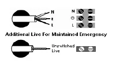
- Permanent Live (L): Brown (Continuous)
- Switched Live (L1): Black (Switched Supply)
- Neutral (N): Blue
- Earth: Green/Yellow
Self Test Procedures
The unit performs automatic self-tests in accordance with BS EN 62034:2012. Upon initial installation, it will randomly select a test date between 200 and 365 days. Once set, it will perform a full 3-hour test annually at the same time.
- Daily: Check that the Green LED is illuminated.
- Monthly: The unit performs a 10-minute functional test.
- Annual: A full 3-hour duration test is performed.
Fault Indicators:
- Continuous Red LED: Battery failure or disconnection.
- Flashing Red LED: System failed the 10-minute or 3-hour duration test.
Maintenance and Disposal
The luminaire contains no user-serviceable parts. The emergency battery pack must be replaced after 3-4 years of use with a 6 Cell NiCd 7.2V 3Ah battery. This product falls under the WEEE Directive and must not be disposed of as normal household waste.
Manufacturer information
Ansell Lighting
Practical help
Common problems
Continuous red LED
Indicates battery failure or disconnection. Check battery leads.
Red LED flashing slowly
Indicates the system failed the 10-minute or 3-hour duration test.
Before use
- Ensure mains supply is switched off before installation.
- Verify compatibility with Ansell AFRLED125, AFRLED170, or AFRLED230.
- Check that the total circuit load does not exceed cable/fuse ratings.
- Ensure correct polarity for electrical connections.
- Do not cover with thermal insulation.
Images and diagrams
- The wiring diagram illustrates the connection points for Permanent Live, Switched Live, Neutral, and Earth.
Model compatibility
- Compatible ONLY with Ansell AFRLED125, AFRLED170, and AFRLED230.

Manual page author
David Miller
Documentation analyst
Organizes user manual content into clear summaries, with attention to model details, product context, and everyday usability.