Lighting / Emergency Lighting
Emergency Lighting Driver IOTA ILBHI CP 2H HE SD HV Instruction Manual
Comprehensive installation and operation guide for the IOTA ILBHI CP 2H HE SD HV LED emergency driver. Includes wiring diagrams, testing procedures, maintenance steps, and troubleshooting.
Quick answers from the manual
Quick answer
- The IOTA ILBHI CP 2H HE SD HV is a 2-hour constant power emergency lighting driver for LED fixtures. It requires an unswitched 347-480 VAC input and provides emergency power for at least 120 minutes. p. 1, 2
Key actions
- Install the unit above the ceiling and wire according to the diagram. p. 2
- Install the Threaded Body Test Switch (TBTS) in a visible location. p. 2
- Perform manual testing by holding the TBTS button for two seconds. p. 4
First start
- Connect AC power and allow the unit to charge for at least 1 hour before testing. p. 3
Problems and fixes
Emergency LED Module does not operate
Check wiring, compatibility, battery charge (1 hour minimum), and TBTS connection.
p. 3Error codes
| Code | Meaning | Action | Pages |
|---|---|---|---|
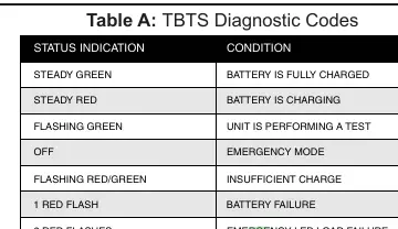
| 1 RED FLASH | BATTERY FAILURE | Check battery/unit status. | p. 4 |
| 2 RED FLASHES | EMERGENCY LED LOAD FAILURE | Check LED load connection. | p. 4 |
| 4 RED FLASHES | TEMPERATURE OUT OF RANGE | Check ambient temperature. | p. 4 |
Maintenance and reset
- Disconnect AC power and disconnect the battery circuit (unplug TBTS or hold button for 5 seconds in emergency mode). p. 4
Technical specifications
| Parameter | Value | Meaning | Pages |
|---|---|---|---|
| Input Voltage | 347-480 VAC | Required unswitched power input. | p. 2 |
| Emergency Duration | 120 Minutes | Minimum operation time in emergency mode. | p. 2 |
Where to find it in the PDF
- Safety and Overview p. 1
- Installation Instructions p. 2
- Operation and Troubleshooting p. 3
- Testing and Maintenance p. 4
Table of contents
Manual images
Click an image to enlargeImportant Information
The IOTA ILBHI CP 2H HE SD HV is a 2-hour constant power emergency lighting driver designed for LED fixtures. It requires an unswitched AC input of 347-480 VAC. The unit features AC Activate technology, which automatically engages the battery charging circuit upon detecting AC power. It is suitable for damp locations and operates in ambient temperatures between 0°C and 55°C.
Installation
Safety First: Before installing, ensure AC power is off and the Threaded Body Test Switch (TBTS) is disconnected.
Mounting
The unit should be mounted on or near the fixture above the ceiling. The flex conduit must be wired into the driver/lamp compartment or an electrical junction box on the fixture.
Wiring
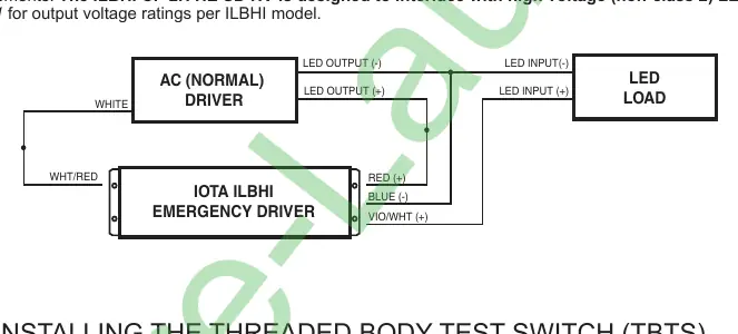
- LED Load and Normal Driver: Refer to the wiring diagram provided in the manual. The unit is designed to interface with high voltage (non-class 2) LED loads.
- AC Input: Connect the BLACK wire to the 347/480 Line and the WHITE wire to the Neutral. The case must be grounded.
TBTS Installation
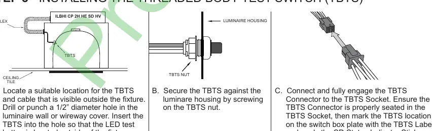
- Locate a suitable position for the TBTS visible outside the fixture.
- Drill a 1/2" diameter hole in the luminaire wall or wireway cover.
- Insert the TBTS and secure it with the TBTS nut.
- Connect the TBTS connector to the socket and apply the status indicator sticker.
Operation
Normal Mode: AC power is present. The AC driver operates the LED module, and the emergency driver is in standby charging mode. The TBTS light indicates the battery is charging.
Emergency Mode: Upon AC power failure, the unit automatically switches to emergency mode, illuminating the LED module at reduced output for a minimum of 120 minutes.
Testing and Maintenance
Testing
- Automatic Testing: The unit automatically tests the emergency function for 60 seconds monthly and 120 minutes annually.
- Manual Testing: Press and hold the TBTS button for two seconds when the status light is GREEN. The test lasts 60 seconds.
Load Calibration
Load calibration is required whenever the connected LED load is changed. It occurs automatically 48 hours after installation or re-initialization. To initiate manually, press and hold the TBTS button for 20 seconds.
Maintenance
To perform maintenance, disconnect AC power and then disconnect the battery circuit by either unplugging the TBTS or pressing and holding the TBTS button for five seconds within the first 30 seconds of emergency mode.
Practical help
Common problems
Emergency LED module does not operate when TBTS button is pressed
Check wiring, ensure LED module is compatible, verify battery has charged for at least one hour, and ensure TBTS is properly inserted.
TBTS charging LED not on
Verify AC power is on and TBTS is properly inserted into the emergency driver socket.
Fixture does not operate in normal mode
Check wiring of the emergency driver and AC driver, and ensure AC power is supplied to the AC driver.
Emergency driver does not operate for at least 120 minutes
Ensure battery is fully charged, LED module is within specifications, or check if the battery is at the end of its life.
Before use
- Ensure AC power is turned off before installation.
- Ensure the TBTS is disconnected before installation.
- Verify the LED load is compatible with the emergency driver.
- Ensure the AC power source is unswitched (347-480 VAC).
- Allow the unit to charge for at least 1 hour before functional testing.
Specs in practice
- Input Voltage
- 347-480 VAC (Must be unswitched).
- Emergency Duration
- Minimum 120 minutes of operation.
- Operating Temperature
- 0°C to 55°C ambient temperature.
Images and diagrams
- Wiring diagram illustrates the connections between the AC (Normal) Driver, the IOTA Emergency Driver, and the LED Load.
- TBTS installation diagram shows the drilling and mounting process for the test switch on the luminaire housing.
Model compatibility
- Designed for grounded LED luminaires listed to UL standards.
- Not for use in heated air outlets or hazardous locations.
- Must be on the same branch circuit as the AC driver.

Manual page author
Emily Carter
User documentation editor
Prepares concise manual descriptions and highlights the most useful setup, operation, and maintenance information for readers.