HVAC / Towel Warmers
Installation Manual for Atlantic Kit 2 Zones
Professional installation and configuration guide for the Atlantic Kit 2 Zones. Includes detailed hydraulic and electrical connection diagrams, circulator settings, and technical specifications for integration with Hysae hybrid gas systems.
Quick answers from the manual
Quick answer
- This is an installation manual for the Atlantic Kit 2 Zones, designed for professional use with Hysae hybrid gas systems. It covers mounting, hydraulic and electrical connections, and circulator configuration. p. 1, 5, 7
Key actions
- Mounting the kit p. 5
- Electrical wiring p. 7, 8
First start
- Verify hydraulic and electrical connections before powering on. p. 5, 7
Problems and fixes
Circulator error (Red blinking)
Check for external faults (voltage/current, blockage). The pump restarts if the problem is fixed.
p. 11Maintenance and reset
- Manual restart of the circulator p. 10
Technical specifications
| Parameter | Value | Meaning | Pages |
|---|---|---|---|
| Power | 95 W | Power consumption | p. 2 |
| Max Pressure | 3 bar | Maximum operating pressure | p. 2 |
Where to find it in the PDF
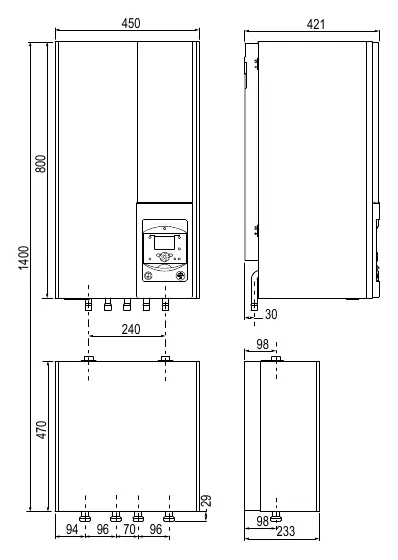
- Dimensions p. 2
- Electrical Wiring p. 8
Table of contents
Manual images
Click an image to enlargeQuick Guide for Installation
This manual is intended for professional installers. Before beginning, ensure the wall is flat and resistant. Verify all components upon receipt to check for transport damage. The installation requires specific hydraulic and electrical connections to the Hysae hybrid gas system.
Product Presentation
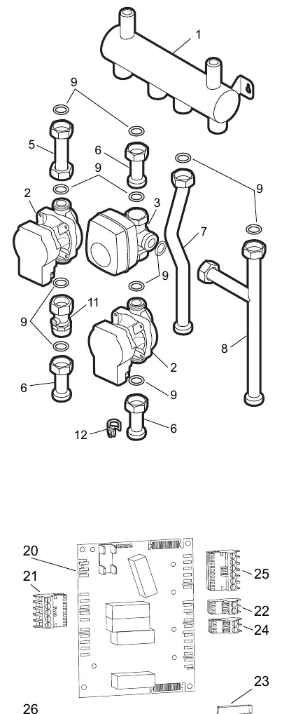
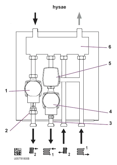
The Kit 2 Zones is designed to manage two heating zones. It includes a circulator, a 3-way mixing valve, and necessary piping. The expansion vessel volume must be determined based on the total installation volume; an additional vessel may be required.
Installation and Mounting
Fix the support securely onto a flat, resistant wall. Ensure the unit is level. The kit must be connected to the installation using union fittings and isolation valves to facilitate future maintenance.
Hydraulic Connections
Connections must comply with current regulations. Use appropriate seals (fiber or O-rings) and sealing paste or tape. Perform the supply/return connections between the Hysae unit and the Kit 2 Zones. If installing a sludge remover (not supplied), place it on the return line between the Hysae and the kit, or on each heating return of the kit.
Electrical Connections
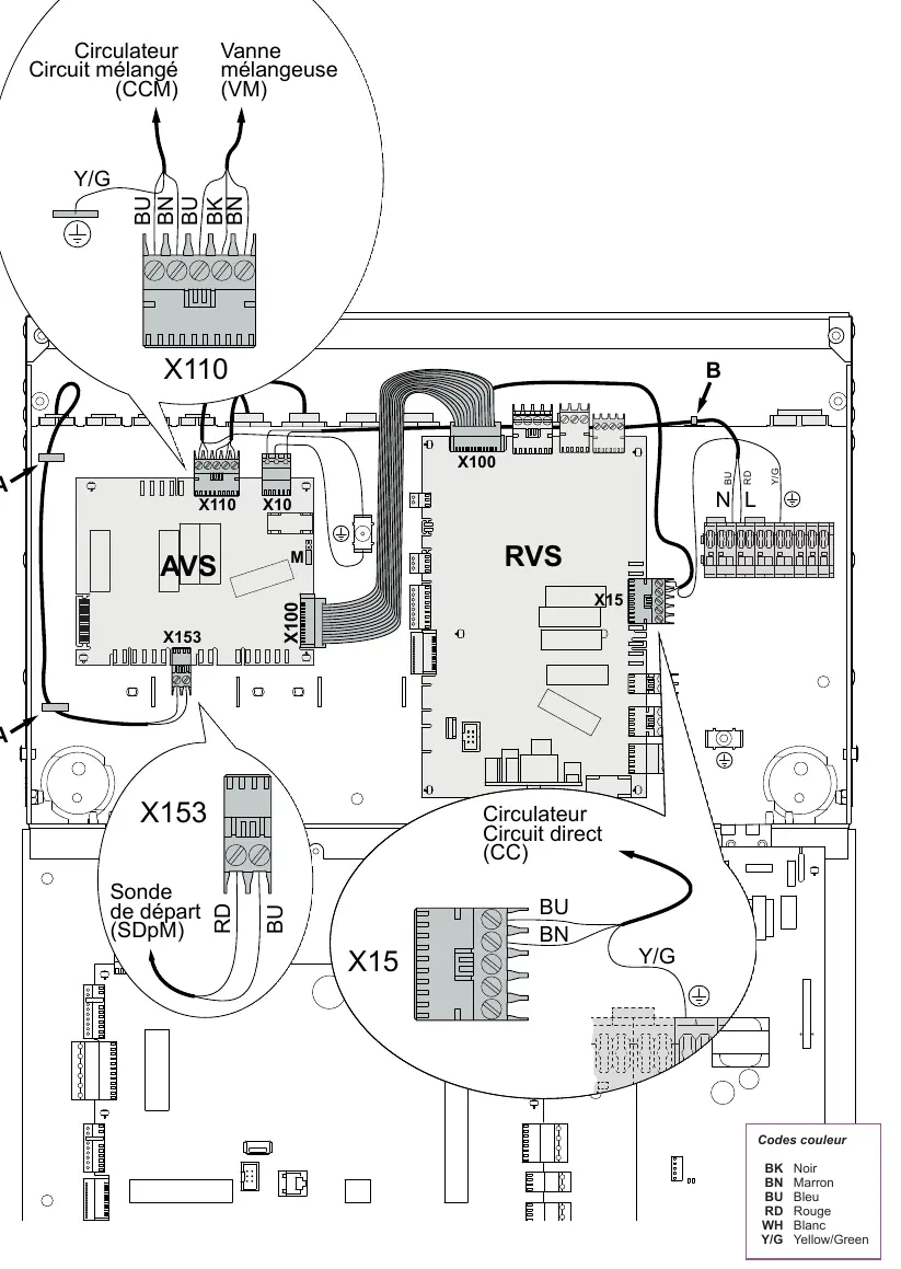
Ensure the main power supply is disconnected before starting. Install the AVS 55 card using the provided clips. Follow the wiring diagram carefully: connect the flow sensor (SDpM) to X153, the ribbon cable between RVS and AVS cards, and the circulators and mixing valve to the specified terminals on the AVS/RVS cards. Verify the position of shunt M.
Circulator Settings
The circulator features different modes: variable pressure (recommended for radiators), constant pressure (recommended for underfloor heating), and constant speed. The default setting is constant pressure, speed I. Use the button on the circulator housing to adjust settings and view the mode/speed.
Troubleshooting and Signals
The circulator indicates status via LEDs:
- Green: Normal operation.
- Green/Red blinking: Alert mode (dry run, motor overload, impurities).
- Red blinking: External fault (voltage/current issue, pump blockage).
- Solid Red: Permanent error, replacement required.
Technical Specifications
- Power consumption: 95 W
- Max operating pressure: 3 bar
- Power supply: 230V - 50Hz
- Connection diameter: 26 x 34 mm
- Mixing valve: 90° travel, 4 min opening/closing time
Practical help
Common problems
Circulator not running
Check if the main power supply is connected and the unit is powered.
Circulator in Alert mode (Green/Red blinking)
Check for dry running, motor overload, or impurities in the water.
Circulator in Error mode (Red blinking)
Check for external faults like abnormal voltage/current or pump blockage. The unit will restart automatically if the issue is resolved.
Before use
- Inspect components for transport damage upon receipt.
- Ensure the wall is flat and resistant (no lightweight partitions).
- Verify the expansion vessel volume is sufficient for the total installation.
- Ensure main power supply is cut off before electrical work.
- Check that all hydraulic seals are properly applied.
Specs in practice
- Power consumption
- 95 W
- Max operating pressure
- 3 bar
- Power supply
- 230V - 50Hz
- Mixing valve travel
- 90 degrees
Images and diagrams
- Fig 1: Dimensions of the Hysae and Kit 2 Zones unit.
- Fig 4: Identification of internal components (circulators, valves, sensors).
- Fig 7: Detailed electrical wiring diagram for AVS and RVS cards.
- Fig 10-14: Circulator interface and settings adjustment.
Model compatibility
- Designed for Hysae hybrid gas systems.
- Requires professional installation.
- Expansion vessel may need to be added depending on total system volume.

Manual page author
Emily Carter
User documentation editor
Prepares concise manual descriptions and highlights the most useful setup, operation, and maintenance information for readers.