Home / Clocks
User Manual for Bodet Style 12 and 12S Digital Clocks
Comprehensive installation and operating guide for Bodet Style 12, 12 Lavable, and 12S digital clocks. Includes wiring diagrams, radio synchronization, configuration settings, and technical specifications.
Table of contents
Manual images
Click an image to enlargeQuick guide from the manual
This manual provides installation and operating instructions for the Bodet Style 12, 12 Lavable, and 12S digital clocks. Key procedures include mechanical mounting, electrical connection to 230V mains, and configuration of time settings using the side-mounted 'Select' and '+' keys. Ensure the clock is installed in a suitable environment and that all wiring is performed by qualified personnel.
Mechanical installation
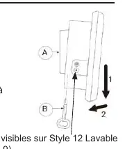
To install the clock, unhook the wall support (A) using the provided square key (B). Fix the support to the wall using the 4 supplied wall plugs and screws. The clock can also be mounted on a vertical bracket, side bracket, or tabletop support (reference 935003). For the Style 12 Lavable, ensure the IP55 protection is maintained.
Electrical power supply
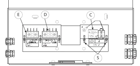
The clock requires a 230 VAC 50/60 Hz power supply. Remove the black protective cover on the terminal block (C) to access the connections. Connect the mains supply and earth, ensuring the wire cross-section is a maximum of 1.5 mm². The installation must include a 10A re-settable circuit breaker. Secure cables using the provided tie wraps (S) and replace the protective cover.
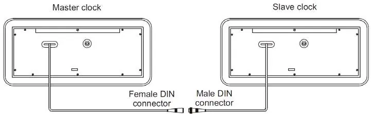
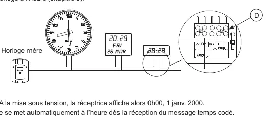
Timing network and radio synchronization
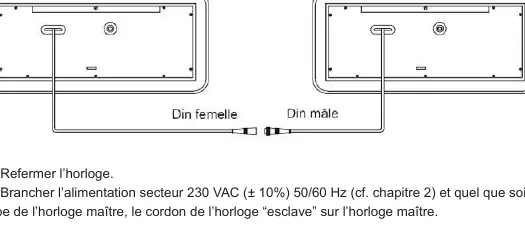
If the clock is part of a timing network, connect the impulse line to the terminal block (D). For parallel distribution, use the '//' and 'COM' terminals. For series distribution, use 'COM' and 'série' terminals, and install the provided 33 Ohm resistor. For radio-synchronized models, orient the antenna (F) until the LED (1) blinks regularly. DHF models are delivered in 'Initialisation' mode and will automatically synchronize upon receiving a signal.
Temperature probe and timer control
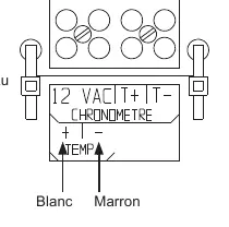
Style 12 models support an optional temperature probe. Connect the probe to the 'TEMP-' and 'TEMP+' terminals on block (E). Avoid placing the probe in direct sunlight, near metal parts, or in draughts. Style 12S models support a timer control unit (ref. 936400). Connect the timer to the 'CHRONOMETRE' terminals on block (E) using a 4-wire cable.
Configuration and time setting
To access the configuration menu, press the 'Select' key for 3 seconds. Use the '+' key to navigate and 'Select' to confirm. You can set the operating mode (Independent, Minute, 1/2 Minute, AFNOR, or DHF), adjust the time, and configure display brightness. If the display is stuck, verify that the operating mode is set to 'Ind' (Independent).
Maintenance and troubleshooting
Clean the clock glass using the provided anti-static cloth; do not use alcohol or acetone. In the event of a power failure, the clock retains settings for 72 hours. If the time is lost after a longer outage, reset it manually via the configuration menu. If the display shows 0°C, check the temperature probe connection.
Practical help
Common problems
Display is stuck at a specific time
Verify that the operating mode is set to 'Ind' (Independent) in the configuration menu.
Temperature probe displays 0°C
The probe is likely connected the wrong way round; check the wiring on terminals TEMP- and TEMP+.
Time is lost after power failure
If the power cut exceeds 72 hours, the time must be reset manually unless the clock is radio-synchronized.
Before use
- Verify package contents: clock, square key, anti-static cloth, and manual.
- Ensure a 230V 50/60 Hz power supply is available.
- Install a 10A re-settable circuit breaker for the power supply.
- Identify your specific model (Style 12, 12 Lavable, or 12S) to determine feature compatibility.
- For radio models, ensure the antenna is oriented correctly.
Specs in practice
- Operating Temperature
- 0 to +50°C for standard models; -5 to +55°C for Style 12 Lavable.
- Power Supply
- 230 VAC ±10% 50/60 Hz.
Images and diagrams
- Terminal block (C) is for 230V mains power connection.
- Terminal block (D) is for timing network (parallel/series) connections.
- Terminal block (E) is for connecting the temperature probe (Style 12) or timer control unit (Style 12S).
Model compatibility
- Temperature probe option is available only on Style 12 models.
- Timer control unit is available only on Style 12S models.
- Style 12 Lavable has an IP55 protection rating.

Manual page author
David Miller
Documentation analyst
Organizes user manual content into clear summaries, with attention to model details, product context, and everyday usability.