Power / EV Chargers
User Manual for BougeRV CIGS Thin-film Solar Panel
Quick guide for BougeRV CIGS Thin-film Solar Panels (Yuma series). Learn about installation, electrical parameters, connection methods, and troubleshooting for your flexible solar setup.
Quick answers from the manual
Quick answer
- The BougeRV CIGS solar panel can be used for off-grid battery systems (requires a charge controller) or connected directly to power stations via MC4 connectors. p. 7
Key actions
- Install the panel by peeling off the adhesive tape or using the drilled holes. p. 7, 13
- Connect panels in series to increase voltage or in parallel to increase current. p. 8
Problems and fixes
Low output power
Check for shading, dust, bird droppings, or high surface temperatures. Ensure the installation angle is optimal.
p. 12Maintenance and reset
- Keep the surface clean and free of debris to prevent hot spots and maintain efficiency. p. 12
Technical specifications
| Parameter | Value | Meaning | Pages |
|---|---|---|---|
| Yuma100 Max Power | 100W | Maximum power output | p. 9 |
| Yuma200 Max Power | 200W | Maximum power output | p. 10 |
Where to find it in the PDF
- Features p. 2
- Dimensions p. 4, 5, 6
- How to Use p. 7, 8
- Electrical Parameters p. 9, 10, 11
Table of contents
Important Information
This manual covers the BougeRV CIGS Thin-film Solar Panel series (Yuma100, Yuma200, Yuma100L). These panels are flexible, lightweight, and designed for various off-grid and power station applications. Ensure you confirm the PV input parameters of your energy storage device before connection.
Features
- Flexible: Can fit around curved structures and various shapes.
- Stable Output: Maintains output even in shadow occlusion environments.
- Waterproof: Suitable for use in wet environments.
- Lightweight: No frames or special mounting brackets required.
- Glass Free: Durable and resistant to breakage.
Installation
There are two primary installation methods depending on the panel version:
- Adhesive: Peel off the protection tape on the rear of the panel and stick it directly to the ground or surface.
- Drilled: Use the pre-drilled holes to mount the panel to your desired surface.
System Connections
Solar Off-grid System
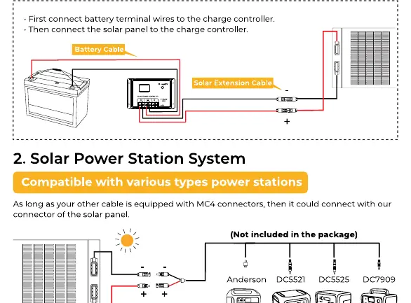
For battery charging, you must use a solar charge controller. Connect the battery terminal wires to the charge controller first, then connect the solar panel to the charge controller.
Solar Power Station System
Compatible with various power stations. As long as your cable is equipped with MC4 connectors, you can connect directly to the power station. Note: Connecting to a power station does not require a solar charge controller.
Series and Parallel Connections
- Series Connection: Wire panels in series to increase the total voltage output.
- Parallel Connection: Wire panels in parallel using a solar parallel connector to increase the total current output.
Troubleshooting
If you experience low or no output, check the following:
- Light Intensity: Ensure the panel is not shaded and is receiving adequate sunlight.
- Installation Angle: Adjust the inclination for optimal sun exposure.
- Temperature: High surface temperatures can reduce output.
- Load Factors: Ensure your energy storage device's input limits are not being exceeded.
- Damage: If the panel is damaged or missing parts, contact [email protected] with your order number.
Manufacturer information
BougeRV
Practical help
Common problems
Low output power
Check for shading, dust, or bird droppings. Ensure the installation angle is optimal and the surface temperature is not excessively high.
No output
Verify all cable connections (MC4). Check if the connected power station or charge controller is compatible and within input voltage/current limits.
Damaged panel or missing parts
Contact BougeRV after-sales support at [email protected] immediately with your order number.
Before use
- Inspect the panel for any physical damage upon receipt.
- Determine the installation method (Adhesive vs. Drilled).
- Confirm compatibility with your charge controller or power station.
- Clean the installation surface.
- Plan your wiring (Series vs. Parallel) based on desired voltage/current.
Specs in practice
- Pmax (Maximum Power)
- The maximum power output of the panel under standard test conditions.
- Voc (Open Circuit Voltage)
- The maximum voltage the panel can produce when not connected to a load.
- Isc (Short Circuit Current)
- The maximum current the panel can produce when the terminals are shorted.
Images and diagrams
- Wiring diagram for off-grid systems showing battery, charge controller, and panel connections.
- Wiring diagram for power station systems showing direct MC4 connection.
- Series connection diagram for increasing voltage.
- Parallel connection diagram for increasing current.
Model compatibility
- Compatible with solar charge controllers for lead-acid and lithium batteries.
- Compatible with power stations via MC4 connectors.
- Requires MC4 connectors for all system connections.

Manual page author
David Miller
Documentation analyst
Organizes user manual content into clear summaries, with attention to model details, product context, and everyday usability.