Smart Home / Sensors Buttons
Casambi BLE 0-10V Ceiling Mounted PIR Sensor with 10A Relay
Quick guide for the Casambi BLE 0-10V Ceiling Mounted PIR Sensor. Includes wiring diagrams, installation precautions, detection patterns, and technical specifications.
Table of contents
Manual images
Click an image to enlargeQuick guide from the manual
This device is a ceiling-mounted PIR sensor designed for presence sensing, daylight harvesting, and 0-10V dimming control within a Casambi mesh network. Important: Do not install the device with power applied. Ensure the sensor is not exposed to moisture, direct sunlight, or placed near heat sources like air conditioners or fans, as these can cause false alarms.
Installation and Wiring
The sensor requires connection to mains power and the 0-10V driver. Ensure all wires are securely held within the connection terminals.
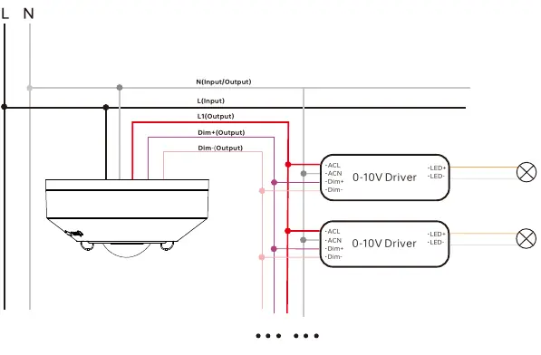
- L (Input): Black, 18 AWG
- N (Input): White, 18 AWG
- L' (Output): Red, 18 AWG
- Dim+ (Output): Violet, 22 AWG
- Dim- (Output): Pink, 22 AWG
Note: With a maximum 20mA 0-10V BUS current output, the sensor can connect to a minimum of 10pcs 0-10V drivers.
Detection Patterns
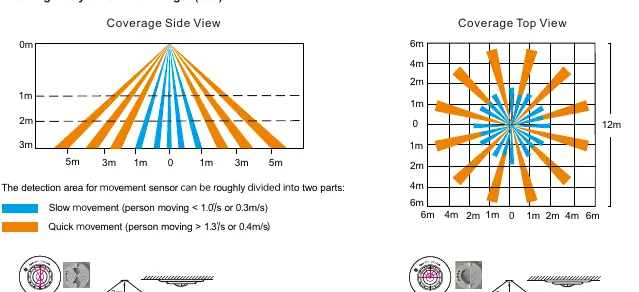
The sensor supports different detection areas based on installation height and lens configuration. Use the provided lens masks to manage the detection pattern for specific applications such as aisles, corridors, or semi-sphere coverage.
Technical Specifications
- Operating Voltage: 100-277VAC 50/60Hz
- Relay Capacity: Resistive Max 10A, Capacitive Max 8A, Inductive Max 7A (all at 120-277VAC)
- Operating Temperature: -10°C to +50°C
- IP Rating: IP20
- Wireless Range: 164 feet (50m) in open field
Practical help
Common problems
Load does not switch on
Verify wiring connections, ensure the sensor is powered, and check if movement is within the detection range.
False alarms
Ensure the sensor is not placed near heat sources (fans, ovens, air conditioners), direct sunlight, or moving objects like trees/bushes.
Before use
- Disconnect power before installation.
- Verify wiring matches the diagram (L, N, L', Dim+, Dim-).
- Ensure the installation location is free from significant air flow and heat sources.
- Configure the lens mask for the desired detection pattern (Aisle or Semi-sphere).
- Check that the load is within the relay capacity (10A resistive).
Specs in practice
- Operating Voltage
- 100-277VAC 50/60Hz
- Relay Capacity
- Max 10A resistive, 8A capacitive, 7A inductive
Images and diagrams
- Wiring Diagram: Illustrates the connection of L, N, L', Dim+, and Dim- to the 0-10V driver.
- Detection Pattern: Shows coverage areas for high-bay and low-bay lenses.
Model compatibility
- Compatible with 0-10V LED drivers.
- Supports up to 10pcs 0-10V drivers with max 20mA BUS current.

Manual page author
Michael Turner
Technical manual editor
Reviews PDF manuals for structure, safety notes, and practical product details so readers can find the right information quickly.