Automotive / Garage Equipment
User Manual for CLÁS PE 2002T, PE 2006T, PE 2007T 2-Post Car Lift
Comprehensive user and installation guide for CLÁS PE 2002T, PE 2006T, and PE 2007T 2-post car lifts. Includes assembly instructions, safety guidelines, operation procedures, and maintenance schedules.
Quick answers from the manual
Quick answer
- This manual provides installation, operation, and maintenance instructions for the CLÁS PE 2002T, PE 2006T, and PE 2007T 2-post car lifts. p. 47, 60
Key actions
- Lifting a vehicle p. 72, 73
- Emergency lowering p. 74
First start
- Perform carriage alignment at first start-up p. 69
Problems and fixes
Lift does not work
Check emergency switch, power supply, cable connections, and fuses.
p. 77Maintenance and reset
- Replace hydraulic oil every 200 operating hours or 5 years p. 76
Technical specifications
| Parameter | Value | Meaning | Pages |
|---|---|---|---|
| Max. lift capacity | 5000 kg | Maximum weight capacity | p. 48 |
Where to find it in the PDF
- Technical Data p. 48
- Installation p. 66, 67, 68
- Operation p. 71, 72, 73
- Maintenance p. 75, 76
Table of contents
Manual images
Click an image to enlargeQuick guide from the manual
This manual provides essential instructions for the installation, operation, and maintenance of the CLÁS 2-post car lift series (PE 2002T, PE 2006T, PE 2007T). Users must read this manual thoroughly before operating the lift. Key safety requirements include ensuring the floor is solid, level, and capable of supporting the lift and maximum load. Only authorized, trained personnel should operate the equipment. Always verify load distribution and stability before lifting.
Device Description
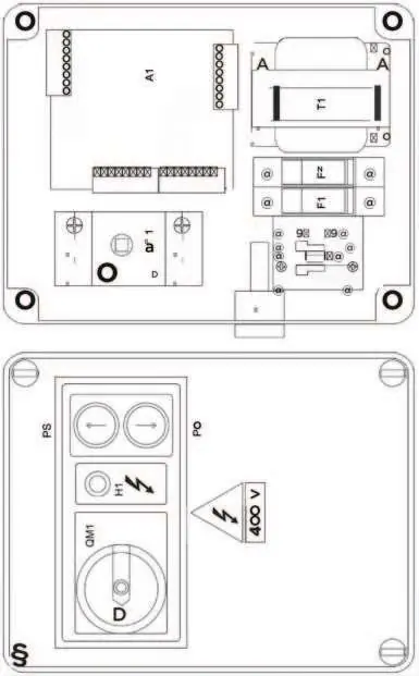
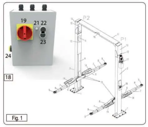
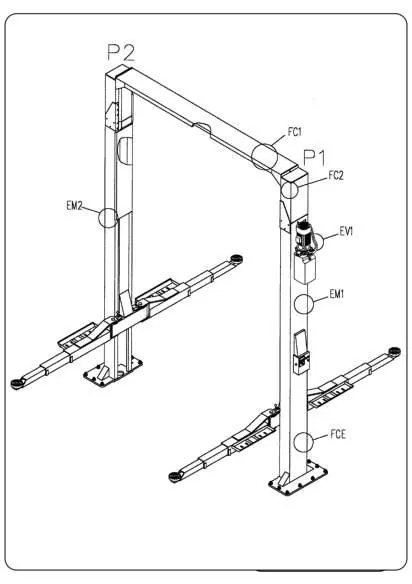
The lift consists of two columns (P1 and P2), carriages, lifting arms, and a crossbeam. The control panel features an emergency switch, voltage warning light, and push-buttons for raising and lowering. Safety devices include mechanical locks, misalignment sensors, and an overhead shut-off bar.
Installation
The lift must be installed on a reinforced concrete floor (class Rck 30, minimum 20 cm thickness). Assembly involves securing columns to the floor, installing the crossbeam, and connecting the hydraulic and electrical systems. Electrical connections must be performed by qualified personnel in compliance with local regulations. The system requires a 3 kW power supply.
Operation
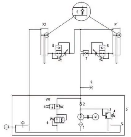
To lift a vehicle, ensure it is centered and load is well-distributed. Turn the emergency switch to ON, position the arms, and press the UP button. The lift features an automatic parking function. To lower, press the DOWN button. In case of power failure, an emergency lowering procedure is available, which involves manually operating the solenoid valve.
Maintenance
Regular maintenance is crucial for safety and longevity. Weekly checks include verifying safety devices and hydraulic oil levels. Monthly checks involve tightening screws and inspecting hydraulic hoses. Every 200 operating hours or 5 years, the hydraulic oil must be replaced.
Troubleshooting
If the lift fails to operate, check the emergency switch, power supply, cable connections, and fuses. If the motor runs but the lift does not move, check the oil level and the discharge solenoid valve. If carriages stop at different heights, perform the alignment procedure.
Practical help
Common problems
Lift does not work
Check if the emergency switch is in the OFF position, verify power supply, inspect cable connections, and check for blown fuses.
Motor runs but lift does not move
Check motor rotation direction, ensure sufficient oil in the tank, and inspect the discharge solenoid valve (EV1).
Carriages stop at different heights
Perform the carriage alignment procedure as described in section 4.4.6.1.
Before use
- Ensure the emergency switch is set to ON
- Verify no unauthorized persons or animals are in the hazardous area
- Check that the vehicle load is well-distributed and centered
- Confirm rubber pads are correctly positioned on the vehicle lifting points
- Check vehicle stability before proceeding with full lift
Specs in practice
- Max. lift capacity
- 5000 kg total load capacity.
- Min. concrete thickness
- 20 cm (class Rck 30) for secure floor anchoring.
- Hydraulic oil
- ESSO NUTO H46 or equivalent (ISO VG 46).
Images and diagrams
- Fig 1: Control panel layout showing emergency switch and operation buttons
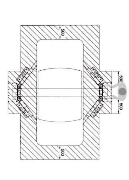
- Fig 3: Load distribution diagram showing maximum weight limits
- Fig 7: Hazardous areas around the lift
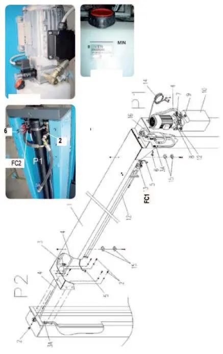
- Fig 16: Hydraulic and electrical connection points
Model compatibility
- Requires 400V 3PH or 230V 3PH/1PH power supply
- Must be installed on a solid, level concrete floor

Manual page author
Emily Carter
User documentation editor
Prepares concise manual descriptions and highlights the most useful setup, operation, and maintenance information for readers.