HVAC / Thermostats & Controls
Installation and Operation Instructions for Copeland 1F79 Heat Pump Thermostat
A comprehensive guide for the Copeland 1F79 non-programmable heat pump thermostat. Includes installation steps, wiring diagrams, configuration menu settings, and troubleshooting procedures.
Quick answers from the manual
Quick answer
- The 1F79 is a non-programmable heat pump thermostat. It requires 20-30 VAC power and supports heat pump systems with or without auxiliary/emergency heat. p. 1
Key actions
- Enter Configuration Menu p. 5
- Reset Thermostat p. 5
First start
- Ensure power is off, mount base, connect wires, install 2 AAA batteries, and set system switch. p. 2
Problems and fixes
Blank Display
Perform a reset by pressing Up and Down keys while switching from OFF to HEAT.
p. 5, 6Maintenance and reset
- Press Up and Down keys simultaneously while switching system from OFF to HEAT. p. 5
Technical specifications
| Parameter | Value | Meaning | Pages |
|---|---|---|---|
| Electrical Rating | 20 to 30 VAC 50/60 Hz | Operating voltage | p. 1 |
| Setpoint Range | 45°F to 90°F | Temperature control range | p. 1 |
Where to find it in the PDF
- Installation p. 2
- Wiring Diagrams p. 3
- Operation p. 4
- Troubleshooting p. 5, 6
Table of contents
Manual images
Click an image to enlargeImportant Information
The Copeland 1F79 is a non-programmable thermostat designed specifically for heat pump systems. It supports systems with or without auxiliary or emergency heat. It is not compatible with standard gas, oil, electric furnaces, or millivolt systems. The unit operates on 20 to 30 VAC and uses 2 AAA alkaline batteries to maintain configuration settings during power loss.
Installation
Before beginning, ensure electrical power is disconnected at the main fuse box. Label all wires with their terminal designations before removing the old thermostat.
- Mounting: Remove the cover, loosen captive screws to remove the base, and mount the base to the wall. Use plastic anchors if necessary.
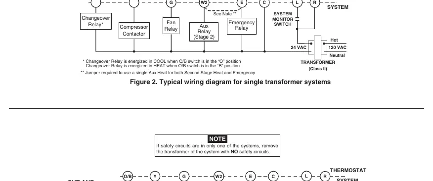
- Wiring: Connect wires to the corresponding terminals on the base. Refer to the wiring diagrams in the manual for specific system configurations (single or two-transformer systems).
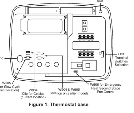
- Jumpers: The base includes jumpers for specific settings:
- W906: Cut if your emergency/auxiliary system energizes the blower.
- W904: Clip to change temperature display to Celsius.
- W905: Clip to change from fast cycle to slow cycle.
Operation
The thermostat features a simple interface with Up/Down arrows for temperature adjustment, a Fan switch (ON/AUTO), and a System switch (COOL, OFF, HEAT, EMER).
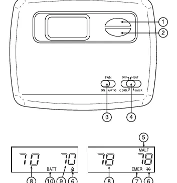
- Heating: Move the system switch to HEAT. Use the Up arrow to set the temperature.
- Cooling: Move the system switch to COOL. Use the Down arrow to set the temperature.
- Emergency Heat: Move the system switch to EMER to bypass the heat pump and use the auxiliary heat source.
Configuration Menu
To enter the configuration menu, set the system switch to OFF, then hold the Up and Down arrow keys simultaneously for at least two seconds. Use this menu to adjust settings such as:
- FA: Fast/Slow cycle selection.
- CL: Compressor Lockout (ON/OFF).
- 0 HI/3 LO: Temperature display adjustment.
- dL: Backlight settings.
Move the system switch out of the OFF position to exit the menu.
Troubleshooting
If the thermostat display is blank or the unit is operating erratically, perform a reset. Press the Up and Down arrow keys simultaneously while switching the system from OFF to HEAT. This resets the unit to factory defaults. Ensure batteries are fresh if the display shows BATT.
Manufacturer information
Copeland
Practical help
Common problems
No Heat/No Cool/No Fan
Check for a blown fuse or tripped circuit breaker, ensure the furnace power switch is ON, and verify the furnace blower door panel is properly installed.
Blank Display or Keypad Not Responding
Perform a reset by pressing the Up and Down keys simultaneously while switching the system from OFF to HEAT.
Cycles too fast
Consider clipping jumper W-905 to enable the slow cycle feature.
Before use
- Label all wires before removing the old thermostat.
- Ensure electrical power is disconnected at the main fuse box.
- Verify your system is a Heat Pump (this model is not for standard furnaces).
- Install 2 AAA alkaline batteries for configuration memory backup.
- Check if your system requires the O/B switch to be in the B position.
Specs in practice
- Electrical Rating
- 20 to 30 VAC 50/60 Hz.
- Setpoint Temperature Range
- 45°F to 90°F (7°C to 32°C).
- Operating Humidity
- 0 to 90% RH (non-condensing).
Images and diagrams
- Figure 1 illustrates the thermostat base, mounting holes, and the location of jumpers W904, W905, and W906.
- Figures 2, 3, and 4 provide wiring schematics for single and two-transformer systems.
Model compatibility
- Compatible with Heat Pump systems (with or without Aux/Emergency heat).
- Not compatible with standard heat/cooling, millivolt, gas/oil, or electric furnaces.

Manual page author
Michael Turner
Technical manual editor
Reviews PDF manuals for structure, safety notes, and practical product details so readers can find the right information quickly.