HVAC / Thermostats & Controls
Installation Guide for Copeland 1E30N-910 Vertical Snap Action Thermostat
Comprehensive installation and operation guide for the Copeland 1E30N-910 vertical snap action thermostat. Includes wiring diagrams, heat anticipator adjustment, troubleshooting steps, and technical specifications.
Quick answers from the manual
Quick answer
- The Copeland 1E30N-910 is a vertical snap action thermostat. Installation involves removing the old unit, labeling wires, mounting the new subbase, connecting wires according to the terminal cross-reference, and adjusting the heat anticipator to match your furnace's current rating. p. 1
Key actions
- Adjusting the heat anticipator p. 1
- Mounting the thermostat p. 1
First start
- After power is turned on, use the system switch to select heating or to turn the heating system off. p. 2
Problems and fixes
No Heat
Check pilot light, anticipator wire, wire connections, or system switch setting.
p. 2Maintenance and reset
- The thermometer can be adjusted using a standard slotted screwdriver to turn the thermometer pointer screw inside the front cover. p. 2
Technical specifications
| Parameter | Value | Meaning | Pages |
|---|---|---|---|
| Switch Rating | 24 VAC (30 VAC max.) | Electrical capacity | p. 2 |
| Heating Amperage | 0.15 to 1.2 Amps | Current rating for heating | p. 2 |
Where to find it in the PDF
- Installation and Setup p. 1
- Operation and Troubleshooting p. 2
Table of contents
Manual images
Click an image to enlargeQuick Guide
This guide provides instructions for installing and operating the Copeland 1E30N-910 vertical snap action thermostat. Before beginning, ensure you have the necessary tools and have disconnected power to the heating system to prevent electrical shock or equipment damage. The most critical adjustments include proper wiring according to the terminal cross-reference and setting the heat anticipator to match your furnace's current rating.
Preparations
Before starting the installation, ensure you have the following tools available:
- Power drill
- Flat blade screwdriver
- Wire cutter/stripper
Removing Old Thermostat
To remove your existing thermostat:
- Disconnect electrical power to the system at the main fuse or circuit breaker.
- Remove the cover (may be snap-on or hinge type).
- Remove the base by unscrewing the mounting screws.
- Label each wire with the terminal designation as you remove it from the old subbase.
Mounting and Wiring
Warning: Do not short out terminals on the gas valve or primary control to test. Short or incorrect wiring will damage the thermostat and could cause personal injury or property damage.
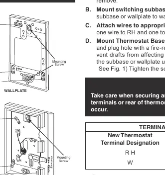
- Remove the base from the subbase or wallplate.
- Mount the subbase or wallplate to the wall using the provided screws.
- Attach wires to the appropriate terminals.
- Gently push excess wire back into the wall opening and plug the hole with fire-resistant material (such as fiberglass insulation) to prevent drafts from affecting thermostat operation.
- Mount the thermostat base to the subbase or wallplate using the three captive screws.
Setting Heat Anticipator
The heat anticipator must be set to match the current rating stamped on your main heating control.
- Move the pointer counterclockwise to lengthen heating system cycles.
- Move the pointer clockwise to shorten heating system cycles.
- Adjustments should not be greater than 1/2 marking at a time.
- For millivolt operation, rotate the contact arm to the Millivolt Link.
Operation
After power is turned on, use the system switch to select heating or to turn the heating system off.
Specifications
- Switch Rating: 24 VAC (30 VAC max.)
- Heating: 0.15 to 1.2 Amps
- Anticipator Rating: Adjustable from 0.15 to 1.2 Amps
- Temperature Range: 50°F to 90°F (10°C to 32°C)
- Operating Humidity Range: 0 – 90% noncondensing
Troubleshooting
If you experience issues, check the following:
- No Heat/No Fan: Check for a blown fuse, tripped circuit breaker, or if the furnace power switch is OFF. Ensure the furnace blower compartment door is properly installed.
- Intermittent Heat: Check for a furnace lock-out condition.
- Heat or Fan Runs Constantly: Check for a short in the wiring or thermostat. Ensure wires are neatly looped under terminals.
- Thermostat Setting and Thermometer Disagree: The thermometer can be adjusted using a standard slotted screwdriver on the pointer screw inside the front cover.
Manufacturer information
Copeland
Practical help
Common problems
No Heat / No Fan
Check for blown fuse/tripped breaker, ensure furnace power switch is ON, and verify the blower compartment door is properly closed.
Heat or Fan Runs Constantly
Check for shorts in wiring or thermostat. Ensure wires are neatly looped under terminals with no stray strands.
Thermostat setting and thermometer disagree
Adjust the thermometer pointer screw located inside the front cover using a standard slotted screwdriver.
Before use
- Disconnect electrical power to the system.
- Label wires before removing the old thermostat.
- Ensure you have a power drill, flat blade screwdriver, and wire cutter/stripper.
- Plug the wall hole with fire-resistant material to prevent drafts.
- Verify the heat anticipator setting matches your furnace's current rating.
Specs in practice
- Switch Rating
- Maximum electrical load the thermostat can handle (24 VAC).
- Anticipator Rating
- Adjustable range (0.15 to 1.2 Amps) to control heating cycle length.
- Temperature Range
- Operating range of the thermostat (50°F to 90°F).
Images and diagrams
- Figure 1 shows the thermostat components including the cover, base, and wallplate.
- Figure 2 illustrates how to adjust the heat anticipator pointer.
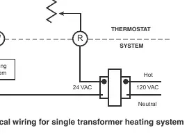
- Figure 3 provides a typical wiring diagram for a single transformer heating system.
Model compatibility
- Compatible with standard heat only systems, electric furnaces, gas/oil heat, and millivolt heat only systems.
- Not for use on circuits exceeding specified voltage.

Manual page author
Emily Carter
User documentation editor
Prepares concise manual descriptions and highlights the most useful setup, operation, and maintenance information for readers.