Toys / RC Models & Drones
User Manual for DJI O4 Air Unit Series
Comprehensive user guide for the DJI O4 Air Unit and O4 Air Unit Pro. Includes installation instructions, wiring diagrams, activation steps, transmission settings, and troubleshooting for video stabilization and EIS issues.
Table of contents
Manual images
Click an image to enlargeQuick Guide from the Manual
The DJI O4 Air Unit Series requires activation via the DJI Assistant 2 (Consumer Drones Series) software before first use. Ensure your power supply meets the voltage requirements (3.7-13.2V for O4 Air Unit; 7.4-26.4V for O4 Air Unit Pro). Proper installation is critical for heat dissipation; mount the unit in a well-ventilated area, preferably near propellers, and ensure antennas are at least 5 cm away from metal or carbon fiber structures.
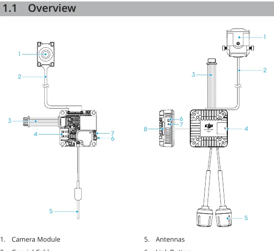
Product Overview
The system consists of a camera module, video transmission module, and antennas. Key components include the USB-C port for data/firmware, a link button for pairing, and a microSD card slot for recording.
Installation and Connection
Important: Do not bend the coaxial cable base. The metal shell becomes hot during operation; do not install in a position easily accessible by hand.
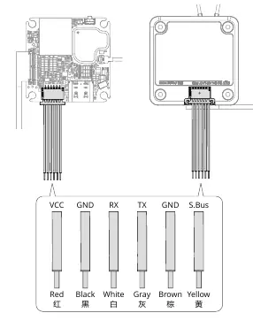
- Wiring: Connect the 3-in-1 cable to your flight controller. The pinout is: Red (VCC), Black (GND), White (UART_RX), Grey (UART_TX), Brown (GND), Yellow (S.Bus).
- Antennas: Must extend out of the aircraft frame and be unobstructed. Maintain a 5 cm distance from the transmission module, camera, and metal/carbon fiber parts.
- Heat Management: Use heat-conductive material to connect the frame and the air unit module to dissipate heat.
Preparation Before Use
Activation: Connect the air unit to a computer via USB-C and use DJI Assistant 2 to activate. Unactivated units have limited transmission power (≤20 mW).
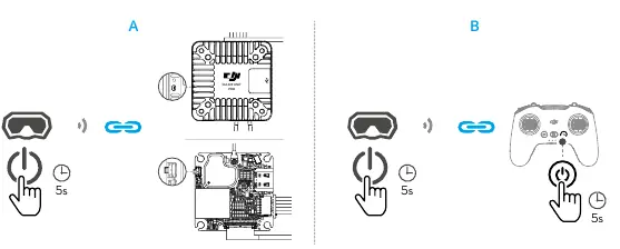
Linking: Power on the air unit, goggles, and remote controller. Use the link button on the air unit and goggles to pair. The linking status indicator will turn solid green upon success.
Usage
Video Recording: Insert a microSD card into the goggles. Recording stops automatically if the card is full, the unit overheats, or the signal is lost.
Transmission Settings: Adjust transmission power and operating channels via the goggles menu. Auto mode selects the best signal strength; Manual mode allows specific bandwidth selection (10/20/40 MHz).
Racing Mode: Supported on specific goggles (e.g., DJI Goggles 3). Disables anti-interference for lower latency; channel must be set manually.
Canvas Mode: Enables OSD elements on the goggles screen. Configure via Betaflight Configurator by setting the MSP switch and defining the serial port.
Troubleshooting EIS and Video Issues
If the video image shakes or exhibits rolling shutter effects:
- IMU Resonance: Ensure the camera is securely mounted. Try changing the ESC PWM control frequency to 48 kHz or 96 kHz. If issues persist, use a softer vibration-absorbing structure.
- Rolling Shutter: Check for damaged propellers and replace if necessary. Adjust the tightness of camera mounting screws.
Official resources from the manual
Manufacturer information
DJI
Practical help
Common problems
Video image shakes (IMU resonance)
Ensure the camera is securely mounted. Change ESC PWM control frequency to 48 kHz or 96 kHz. If it persists, use a softer vibration-absorbing structure between the camera and frame.
Rolling shutter effect
Replace damaged propellers. Adjust the vibration-absorbing structure or tighten the camera mounting screws.
Overheating/Low-power mode
Ensure the unit is installed in a well-ventilated area, preferably near propellers. Use heat-conductive material to connect the module to the frame.
Before use
- Activate the device using DJI Assistant 2 (Consumer Drones Series).
- Update firmware to the latest version.
- Verify power supply voltage: 3.7-13.2V (Air Unit) or 7.4-26.4V (Pro).
- Check wiring sequence: Red (VCC), Black (GND), White (RX), Grey (TX), Brown (GND), Yellow (S.Bus).
- Ensure antennas are at least 5 cm away from metal/carbon fiber parts.
Images and diagrams
- Wiring diagram shows color-coded connections for the 3-in-1 cable.
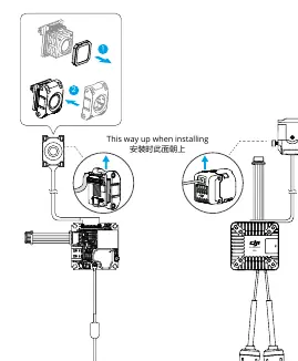
- Installation diagram illustrates the correct upward orientation for the camera module.
Model compatibility
- Racing mode requires DJI Goggles 3 or DJI Goggles N3.
- Canvas Mode requires Betaflight Configurator 4.3.0 or later.

Manual page author
Michael Turner
Technical manual editor
Reviews PDF manuals for structure, safety notes, and practical product details so readers can find the right information quickly.