HVAC / Air Conditioners
Installation Manual for Dometic RTX 1000/2000 Air Conditioning Unit
Quick installation guide for the Dometic RTX 1000 and RTX 2000 parking cooler. Includes roof cutout dimensions, sealing instructions, bolt length calculations, and electrical connection steps.
Table of contents
Manual images
Click an image to enlargeQuick guide from the manual
This document provides visual installation instructions for the Dometic RTX 1000 and RTX 2000 air conditioning units. The installation process relies on specific roof cutout dimensions and precise bolt length calculations based on the thickness of the vehicle roof. Ensure you have the correct mounting kit and tools before beginning.
Roof cutout and preparation
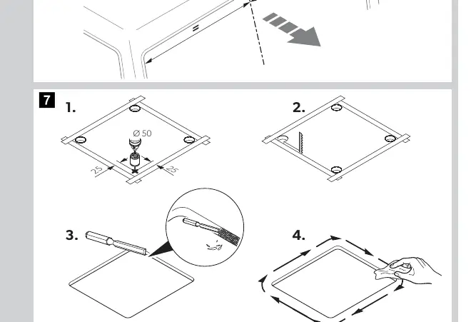
The unit requires a specific roof opening to be prepared. The standard cutout dimensions are 500mm by 400mm. Ensure the roof surface is clean and level before proceeding with the installation. Verify that the surrounding area allows for the specified clearances (at least 100mm on sides) to ensure proper airflow.
Sealing and mounting
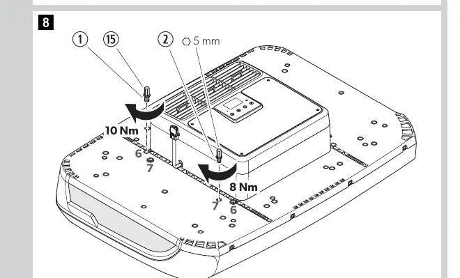
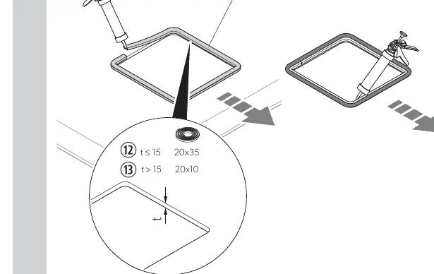
Proper sealing is critical to prevent leaks. Apply the seal to the unit base according to the thickness of the roof (t). Use the provided mounting hardware to secure the unit to the roof. Tighten the mounting bolts to the specified torque settings: 10Nm for the primary bolts and 8Nm for the secondary securing points. Do not overtighten.
Bolt length calculation
The length of the mounting bolts (L1, L2, L3) must be calculated based on the thickness of the roof (x). Use the following formulas provided in the manual to determine the correct bolt length for your specific vehicle:
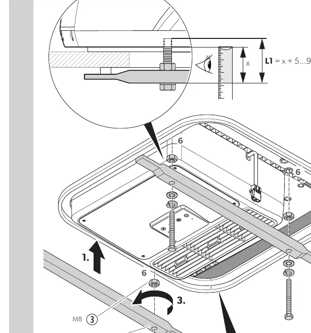
- L1 = x + 5...9mm
- L2 = x + 23...27mm
- L3 = x + 9mm
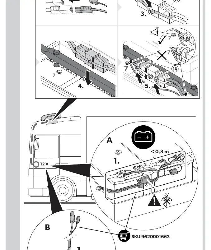
Electrical connection
The unit is designed for 12V systems. The electrical connection must be made as close to the power source as possible, with a maximum cable length of 0.3 meters to ensure optimal performance and safety. Ensure all connections are secure and protected from moisture.
Manufacturer information
Dometic
Practical help
Common problems
Incorrect bolt length
Calculate L1, L2, and L3 based on your specific roof thickness (x) using the formulas provided in the manual.
Leaking seal
Ensure the roof surface is clean and the seal is applied evenly before mounting the unit.
Before use
- Verify roof thickness (x) to calculate correct bolt lengths.
- Ensure the roof cutout is exactly 500x400mm.
- Check that the electrical connection is within 0.3m of the power source.
- Use a torque wrench to tighten bolts to 10Nm and 8Nm.
- Ensure at least 100mm clearance around the unit on the roof.
Images and diagrams
- Step 6-7: Shows the roof cutout dimensions and preparation.
- Step 8: Shows the initial mounting of the unit to the roof.
- Step 11-13: Shows the calculation of bolt lengths based on roof thickness.
Model compatibility
- Designed for 12V systems.
- Universal 3 mounting kit.

Manual page author
Emily Carter
User documentation editor
Prepares concise manual descriptions and highlights the most useful setup, operation, and maintenance information for readers.