Power / Solar Inverters
Dometic Enerdrive 12V True Sine Wave Inverter User Manual
Quick guide for Dometic Enerdrive 12V True Sine Wave Inverters (1000W/2000W). Includes installation, wiring, operation, troubleshooting, and technical specifications.
Table of contents
Manual images
Click an image to enlargeQuick Guide
This manual provides instructions for the Dometic Enerdrive 12V True Sine Wave Inverter series (1000W and 2000W). These units provide AC power and 5V USB power for homes, boats, caravans, and vehicles. Important: All wiring should be performed by a certified technician. The unit must be installed in an area with at least 75mm of clearance for ventilation and must not be installed in corrosive environments or zero-clearance compartments.
Product Description
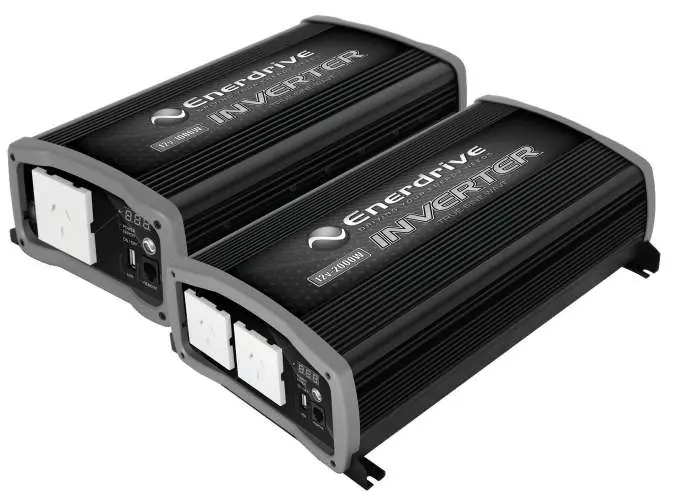
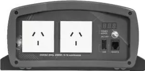
The package includes the inverter base unit and the owner's manual. The front panel features AC output sockets, a USB output, an On/Off switch, and a remote plug. The rear panel contains the fan opening and DC input terminals (Positive/Negative).
Installation
Proper installation is critical for safety and performance. Follow these steps:
- Mounting: Choose an appropriate location. For RVs, mount horizontally. For indoor use, mount in any direction except with the DC input panel facing downwards.
- Wiring: Use low-resistance wire for all DC connections. EN1110S requires a minimum 35mm² wire; EN1120S requires a minimum 70mm² wire. Maximum cable length is 1.5 meters.
- Fuse/Circuit Breaker: A DC-rated fuse or circuit breaker must be installed on the positive line. EN1110S requires a minimum 150 Adc; EN1120S requires a minimum 250 Adc.
- Grounding: The chassis must be grounded properly using the ground stud located near the DC input terminal.
- DC Connection: Connect the negative cable to the battery negative terminal and the positive cable through the fuse/breaker to the battery positive terminal.
Operation
Turning ON/OFF USB only: Press and hold the Power/Select button for 1 second until a single beep sounds. The display will show USB, and the status LED will turn green. This mode saves battery power if AC is not required.
Turning ON/OFF 230 VAC and USB: Press and hold the Power/Select button for 2 seconds until 2 beeps sound. The display will show battery voltage and output power. The status LED will turn green.
Troubleshooting
The inverter uses error codes to indicate issues:
- E01: Input under voltage. Recharge battery immediately.
- E02: Input over voltage. Check battery voltage or external chargers.
- E03: Overload or short circuit. Reduce load and restart.
- E04: Internal temperature high. Turn off and wait 15 minutes.
- E05: Input voltage low. Recharge battery.
- E06: Load close to overload limit. Reduce load.
- E07: Internal temperature high/ventilation blocked. Reduce load and check ventilation.
Specifications
The Enerdrive Inverter series operates on a 12V DC input (10.5 - 15.5 VDC range). The 1000W model provides 4.3A AC output, while the 2000W model provides 8.7A AC output. Both models feature a 5V, 750mA USB output and operate within a temperature range of 0°C to 40°C.
Manufacturer information
Dometic
Practical help
Common problems
No output voltage and Status LED is off
Turn the unit ON using the Power/Select button or check if the DC fuse/disconnect switch is blown or turned off.
Status LED is Amber
A warning is detected. Check the error code on the display and refer to the troubleshooting section.
Status LED is Red
An error is detected and the unit has shut down. Check the error code on the display.
E03 Error Code
The unit has sensed an overload or short circuit. Reduce the load connected to the AC output and restart the unit.
Before use
- Ensure wiring is performed by a certified technician.
- Verify the battery bank is 12V.
- Install a DC-rated fuse or circuit breaker on the positive line.
- Ensure the chassis is properly grounded.
- Allow at least 75mm of space around the unit for ventilation.
- Ensure the DC input panel is not facing downwards.
Specs in practice
- AC Output Voltage
- 230 VAC / 50 Hz
- DC Input Voltage Range
- 10.5 - 15.5 VDC
- EN1110S Fuse Requirement
- Minimum 150 Adc
- EN1120S Fuse Requirement
- Minimum 250 Adc
Images and diagrams
- Wiring Diagram: Illustrates the connection from the 12V battery bank through a fuse/circuit breaker to the inverter.
- Front Panel: Identifies the AC output, USB output, On/Off switch, and Remote plug locations.
- Rear Panel: Identifies the fan opening, positive terminal, and negative terminal.
Model compatibility
- Not for use with life support systems or medical equipment.
- Requires deep cycle battery for optimal performance.
- EN1110S requires minimum 35mm² wire.
- EN1120S requires minimum 70mm² wire.

Manual page author
David Miller
Documentation analyst
Organizes user manual content into clear summaries, with attention to model details, product context, and everyday usability.