Power / Solar Inverters
ECO-WORTHY 10KW AIO Inverter User Manual
Comprehensive user guide for the ECO-WORTHY 10KW AIO Inverter. This manual covers installation, wiring diagrams for single and parallel systems, operation settings, fault codes, and maintenance instructions.
Table of contents
Manual images
Click an image to enlargeQuick guide from the manual
This manual provides essential instructions for the installation, operation, and maintenance of the ECO-WORTHY 10KW AIO Inverter. Before starting, ensure you have read the safety section and understand the wiring requirements for your specific system configuration (single or parallel). Always disconnect circuit breakers before performing any wiring or maintenance to avoid electric shock.
Product overview
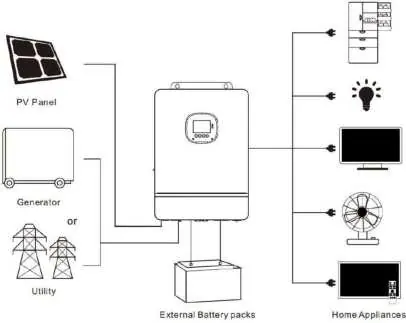
The SPI series solar storage inverter integrates PV storage, mains charge, and energy storage. It outputs sinusoidal AC and features DSP control. Key features include dual-channel MPPT, support for various battery types (lead-acid and lithium-ion), and multiple output modes (mains bypass or inverter output).
Installation
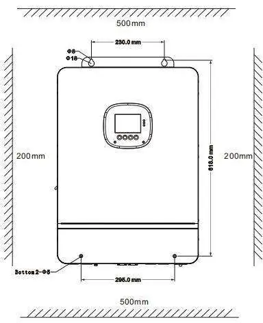
The inverter is designed for indoor use (IP20 protection level). Ensure the installation location is a solid wall with sufficient heat dissipation space and an ambient temperature between -10°C and 55°C. Do not install near flammable materials or in explosive areas. Use an electric drill to create 4 holes, insert expansion screws, and fix the inverter using M5 screws.
Wiring
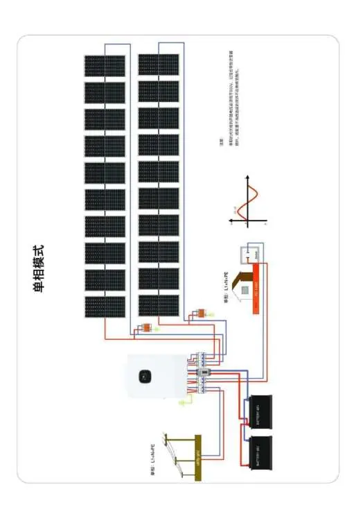
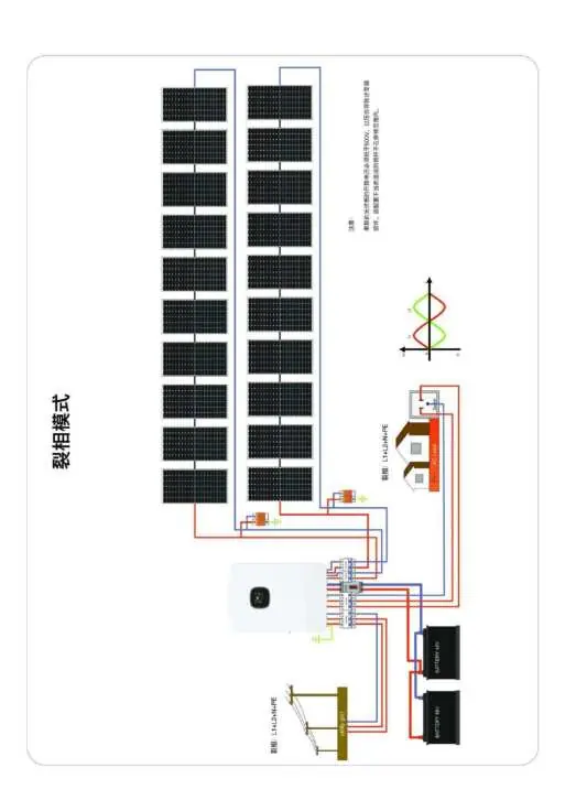
Wiring must be performed according to the specific output mode (split-phase or single-phase). Ensure correct cable sizes and circuit breakers are used as specified in the manual. Connect PV, AC input/output, and battery terminals securely. For parallel operation, connect the parallel communication cables between inverters. Always verify wiring sequence before powering on.
Operation
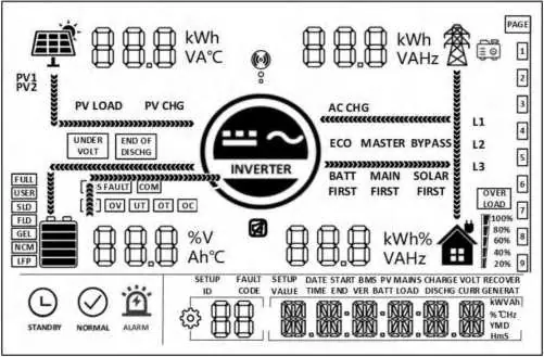
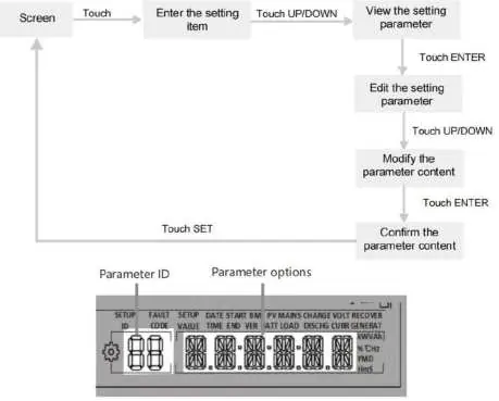
The inverter features an LCD screen, LED indicators, and physical buttons for navigation. Users can configure parameters such as AC output mode, battery type, and charge current. Real-time data can be viewed on the screen by pressing the UP/DOWN buttons. The system supports timed charge/discharge functions to optimize electricity costs.
Communication
The device includes USB-B, WIFI, RS485/CAN, and dry contact ports. The WIFI port connects to a data acquisition module for mobile app monitoring. The RS485/CAN port is used for BMS communication with lithium-ion batteries. The dry contact port supports remote ON/OFF, signal output, and generator start/stop functions.
Troubleshooting
If a fault occurs, the fault code will be displayed on the screen. Common issues include battery under-voltage, overload, or fan failure. Refer to the fault code table to identify the meaning and follow the suggested solutions. If a problem persists, contact ECO-WORTHY support.
Maintenance
Regular maintenance is recommended twice a year. Ensure airflow around the inverter is smooth, clean the dust-proof net, check for damaged insulation on wires, and verify that all terminals are tight and free of corrosion. Always disconnect all power sources before inspection.
Practical help
Common problems
No screen display
Check if the battery air-switch or PV air-switch is closed; ensure the device switch at the bottom is ON; press any button on the screen to exit sleep mode.
Battery under-voltage
The battery voltage is lower than the value set in parameter [14]. Charge the battery until the voltage exceeds the set threshold.
Overload
The output power or current is overloaded. Reduce the load power and restart the device.
Fan fault
Shut down the device, manually check the fan, and ensure no foreign objects are blocking it.
Mains input phase fault
The phase of the AC input is inconsistent with the AC output. Ensure the AC input phase matches the output phase.
Before use
- Ensure the installation location is a solid wall with sufficient heat dissipation space.
- Verify the ambient temperature is between -10°C and 55°C.
- Check that all wiring terminals are tight and free of corrosion.
- Ensure the grounding terminal is reliably connected.
- Confirm all circuit breakers are disconnected before starting wiring.
- Verify the battery type and parameters are correctly set in the menu.
Specs in practice
- Rated output power
- 10,000 W continuous power output.
- Maximum PV input voltage
- 500 Vdc; exceeding this will damage the inverter.
- Rated battery voltage
- 48 Vdc system voltage.
- Protection level
- IP20; suitable for indoor use only.
- MPPT efficiency
- 99.9% efficiency for solar charging.
Images and diagrams
- System connection diagram: Illustrates the integration of PV panels, generator/utility grid, battery packs, and household loads.
- Wiring diagrams: Detailed schematics for single-phase and split-phase parallel connections for up to six inverters.
Model compatibility
- Supports lead-acid (Sealed, Gel, Flooded) and lithium-ion (LFP, Ternary) batteries.
- Supports parallel operation of up to six solar storage inverters.
- Requires specific cable sizes (e.g., 13mm²/6 AWG for AC output) based on the model.

Manual page author
David Miller
Documentation analyst
Organizes user manual content into clear summaries, with attention to model details, product context, and everyday usability.