Power / Solar Inverters
User Manual for SolaX X3-Hybrid Series Inverter
Comprehensive user manual for the SolaX X3-Hybrid series inverter (5.0kW-15.0kW). Includes installation, electrical connection, work modes, settings, and troubleshooting guides.
Table of contents
Manual images
Click an image to enlargeQuick Guide from the Manual
The SolaX X3-Hybrid series is an energy storage inverter supporting photovoltaic grid-connected systems. This manual covers models ranging from 5.0kW to 15.0kW. Before installation, ensure the inverter is fixed on a solid wall, all ground wires are connected, and DC/AC breakers are disconnected. The inverter is IP65 rated, suitable for outdoor use, but must be kept away from direct sunlight, rain, and snow.
Introduction
The inverter converts solar energy into AC power, stores energy in batteries, and can feed excess power into the public grid. It provides emergency power during outages. Key work modes include:
- Self Use: Optimizes self-consumption; PV powers loads, charges battery, then sells to grid.
- Feed-in Priority: Prioritizes selling to the grid after battery charging.
- Backup Mode: Maintains high battery capacity for frequent power outages.
- EPS (Off-grid) Mode: Provides emergency power during grid failure (requires battery).
Installation
Ensure the installation site is away from flammable materials and has adequate space for heat dissipation (at least 300mm on all sides). The inverter must be mounted with a maximum back tilt of 5 degrees. Use the provided wall-mount bracket and expansion bolts for secure installation.
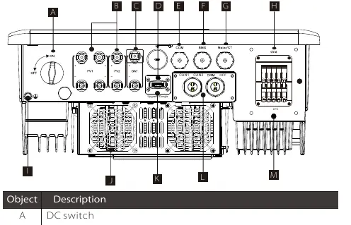
Electrical Connections
PV Connection: Ensure open circuit voltage is below the maximum limit (1000V). Use the provided PV terminals and ensure correct polarity.
Grid and EPS Connection: Connect the grid and EPS loads according to the specific wiring diagrams provided for your region (e.g., Australia vs. other countries). Use the recommended cable sizes and micro-breakers.
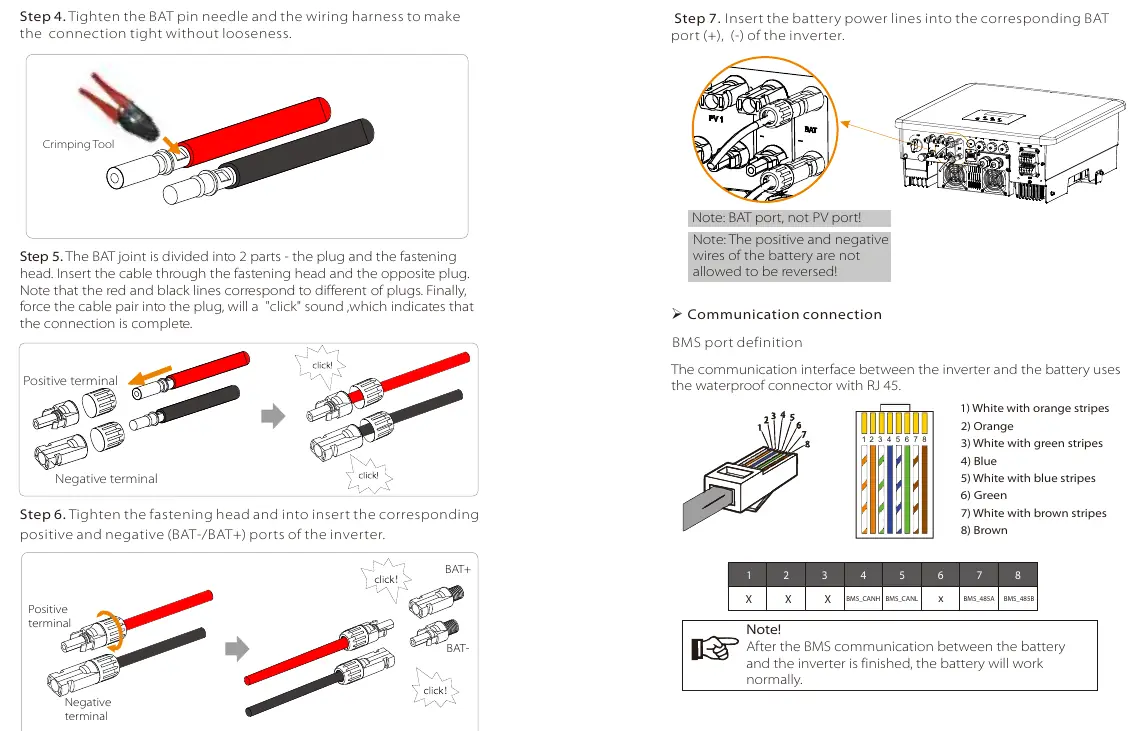
Battery Connection: Connect high-voltage lithium batteries using the BAT terminals. A non-polar DC MCB must be installed for safety.
Communication: The inverter supports various communication protocols including DRM, Meter/CT, and parallel communication. Use the specified RJ45 pin definitions for each port.
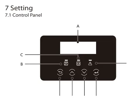
Settings and Operation
The control panel features an LCD screen and LED indicators. Use the menu to configure settings such as date/time, language, safety standards, and work modes. The system automatically enters the setup guide upon first boot.
Troubleshooting
If a fault occurs, check the error code on the LCD screen. Common issues include:
- Overload: Ensure EPS load is within rated output power range.
- Meter Failure: Check meter or CT connection.
- Inverter stuck after upgrade: Turn off PV power supply and restart.
Maintenance
Regularly check the heat sink for dirt and clean with a soft dry cloth. Perform safety inspections at least every 12 months. Check input/output lines for damage or aging every 6 months.
Practical help
Common problems
Inverter displays 'overload' warning
Ensure EPS load is within the rated output power range. Adjust load power if necessary.
Meter failure alarm
Check that the meter or CT is correctly connected to the inverter.
Inverter stuck on 'X3-Hybrid G4' after firmware upgrade
Turn off the photovoltaic power supply and restart the inverter.
Inverter reports ISO Fault
Check if the PV end is properly connected to earth.
Before use
- Check for transport damage
- Ensure installation surface is solid and can support the weight
- Verify PV input voltage is within the MPPT range
- Check all ground connections are secure
- Confirm battery compatibility and connection
- Ensure all DC and AC circuit breakers are disconnected before wiring
Specs in practice
- Max. DC voltage
- Maximum voltage the inverter can handle from PV panels (1000V).
- EPS(Off-grid) rated power
- Maximum power output available during grid power outages.
- Ingress Protection
- IP65 rating, indicating the unit is dust-tight and protected against water jets.
- Operating temperature range
- -35°C to +60°C (derating at 45°C).
Images and diagrams
- Wiring diagrams for D and M series inverters
- Parallel connection diagrams for multi-inverter systems
- Communication port pinouts for BMS, Meter/CT, and DRM
Model compatibility
- Compatible with high voltage lithium batteries
- Requires authorized meter/CT for proper operation
- Supports parallel connection of up to 10 inverters

Manual page author
Emily Carter
User documentation editor
Prepares concise manual descriptions and highlights the most useful setup, operation, and maintenance information for readers.