Power / Portable Power Stations
Installation Guide for EcoFlow Smart Gateway (200A)
Comprehensive installation guide for the EcoFlow Smart Gateway (200A). Includes mounting instructions, wiring diagrams, technical specifications, and safety guidelines for professional installation.
Quick answers from the manual
Quick answer
- The EcoFlow Smart Gateway (200A) is a service equipment panel. Installation requires qualified personnel, adherence to local electrical codes, and specific wiring/mounting procedures detailed in this guide. p. 3, 6
Key actions
- Mounting the panel p. 10
Technical specifications
| Parameter | Value | Meaning | Pages |
|---|---|---|---|
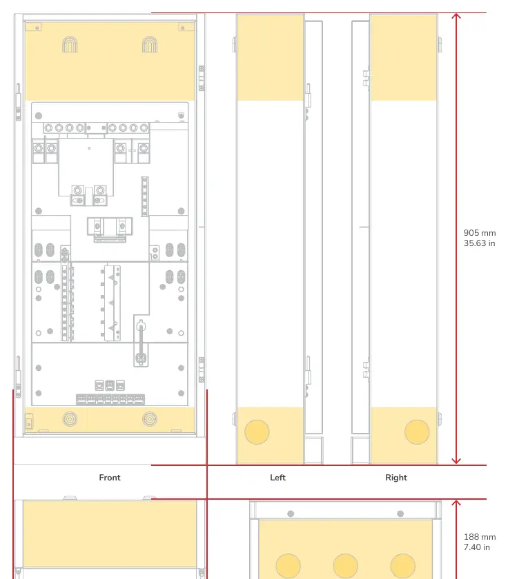
| Dimensions | 905 x 385 x 188 mm | Physical size of the unit | p. 4 |
Where to find it in the PDF
- Product Overview p. 7
Table of contents
Manual images
Click an image to enlargeImportant Information
This document provides essential installation instructions for the EcoFlow Smart Gateway (200A). Installation must be performed by qualified personnel in accordance with local electrical standards and the National Electrical Code (ANSI/NFPA 70). Always use appropriate personal protective equipment (PPE) and ensure all power sources are disconnected before servicing.
Product Overview
The unit features several key modules:
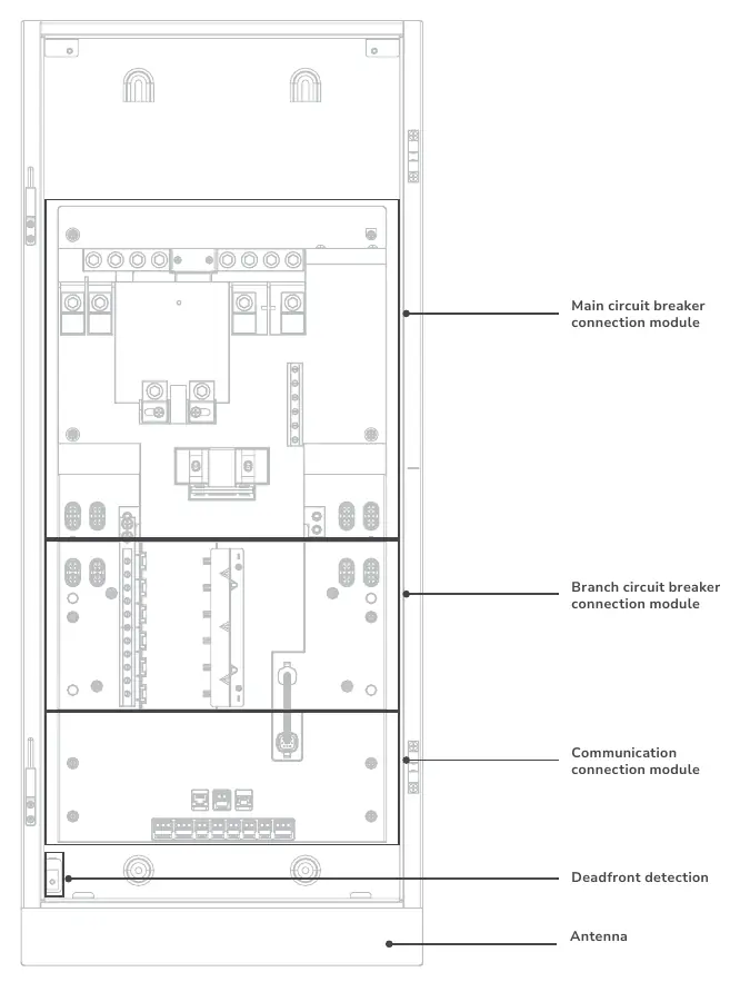
- Main circuit breaker connection module
- Branch circuit breaker connection module
- Communication connection module
- Deadfront detection
- Antenna
Installation
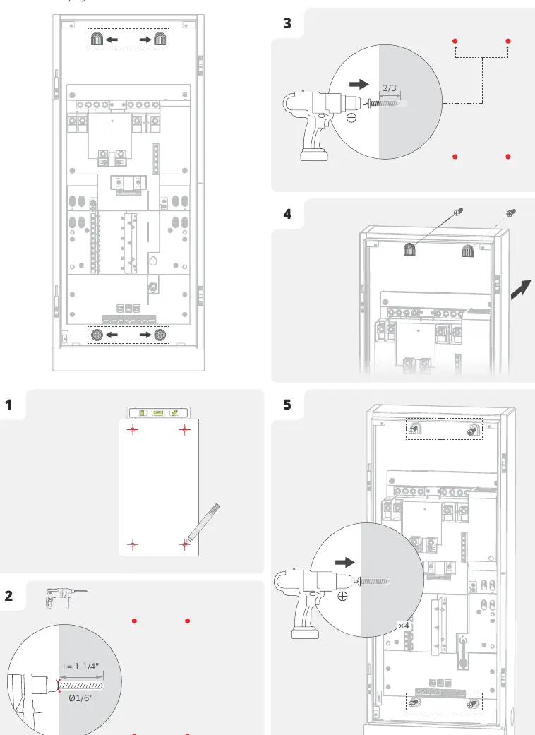
The panel supports surface or semi-flush mounting. Ensure proper clearance: keep 1.5 inches from the door swing side to allow the door to open to 90°. For semi-flush mounting, the recess depth must not exceed 4-3/4" (120.5 mm).
Cable Entry
There are 5 preset expandable knockouts (1-7/8" for 1-1/2" conduits). If drilling additional entries, cover the interior equipment to prevent debris from entering. A hydraulic hole puncher is recommended.
Mounting the Panel
- Mark and pre-install four screws into the wall, leaving approximately 1/3 of each screw exposed.
- Mount the panel onto the screws.
- Fully tighten all four screws to secure the unit.
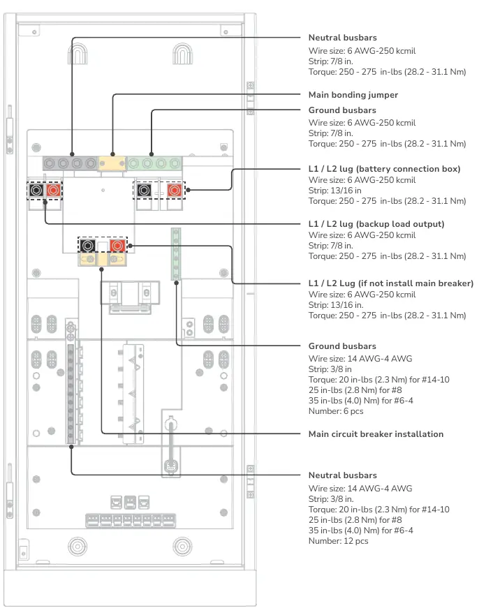
Wiring
Ensure power is off and main/branch breakers are in the OFF position before wiring. Use conductors rated to a minimum of 75°C (165°F). Refer to the specific torque requirements for each connection point, typically ranging from 20 in-lbs to 275 in-lbs depending on the terminal type.
Communication
The communication module includes various ports for system integration:
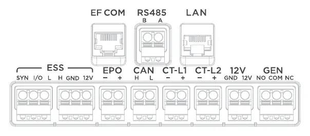
- EF COM: Connects with EcoFlow Smart Inlet Box
- LAN: Ethernet connection
- ESS: Connects with EcoFlow OCEAN Pro Hybrid Inverter
- EPO: Emergency Power Off (connect according to local regulation)
- CAN: EV charger
- CT1/CT2: Connects with CT
- GEN: Connects with generator
EcoFlow Smart Inlet Box Installation
The Smart Inlet Box is designed for use with the Smart Home Panel 2. Ensure the box is installed in a location that prevents water damage. Follow the steps to unscrew the cover, mount the box to the wall, perform the wiring, and re-install the cover.
Manufacturer information
EcoFlow
Practical help
Common problems
Panel door does not open to 90 degrees
Ensure 1.5 inches of clearance from the door swing side.
Debris inside equipment during drilling
Cover interior equipment before drilling and clear debris afterward.
Before use
- Verify power is off before wiring
- Use appropriate PPE (goggles, gloves, safety shoes)
- Ensure main and branch breakers are in OFF position
- Check wire sizes and torque specifications
- Confirm grounding connections
Specs in practice
- Enclosure Protection
- NEMA 3R, Rainproof
- Rated Input Voltage
- 120/240V, 60Hz
- Maximum Continuous Current
- 160A
Images and diagrams
- Product Overview shows main and branch circuit breaker modules
- Cable entry locations are highlighted in yellow on the front, top, bottom, left, and right sides
- Communication ports include EF COM, LAN, ESS, and others
Model compatibility
- Main circuit breaker: 100-200A
- Branch circuit breaker: 125A Max, AFCI/GFCI supported, plug-in type

Manual page author
Emily Carter
User documentation editor
Prepares concise manual descriptions and highlights the most useful setup, operation, and maintenance information for readers.