Industrial / Process Controllers
User Manual for Emerson 16E09-101 Electronic Temperature Control
Comprehensive user guide for the Emerson 16E09-101 Electronic Temperature Control. Includes installation, wiring diagrams for power stealing and non-power stealing applications, menu settings, operation modes, and troubleshooting.
Quick answers from the manual
Quick answer
- The 16E09-101 is a single-stage electronic temperature control for refrigeration or heating. It features user-configurable settings for differential, anti-short cycle delay, and alarms. It supports both Power Stealing and Non-Power Stealing wiring configurations. p. 1
Key actions
- Enter Menu p. 4
- Reset to Factory Defaults p. 4
- Unlock Keypad p. 4, 6
First start
- Set System Mode (SW1) p. 2
- Set Wiring Mode (SW2) p. 3
Problems and fixes
Display indicates 'CaL' on power up
Control was not calibrated. Return control for replacement.
p. 8
Unit does not turn on
Check wiring, power, and that switches are set to proper positions.
p. 8Maintenance and reset
- Reset to factory defaults p. 4
Technical specifications
| Parameter | Value | Meaning | Pages |
|---|---|---|---|
| Temperature Range | -40° to 220°F (-40° to 104°C) | Operating temperature range of the control. | p. 1, 7 |
| Load Relay | SPDT | Single Pole Double Throw output load relay. | p. 1 |
| Enclosure | NEMA 1 | Enclosure rating. | p. 1, 7 |
Where to find it in the PDF
- Description and Precautions p. 1
- Installation and Dimensions p. 2
- Wiring Diagrams p. 3
- User Menu Settings p. 4, 5
- Operation Details p. 5, 6
- Specifications p. 7
- Troubleshooting p. 8
Table of contents
Manual images
Click an image to enlargeQuick guide from the manual
The Emerson 16E09-101 is a single-stage electronic temperature control designed for refrigeration and heating applications. Before installation, it is critical to determine if your system requires Power Stealing or Non-Power Stealing wiring, as this dictates the switch settings and wiring configuration. Always set the system mode (Heating/Cooling) using switch SW1 before configuring menu options.
Description
The 16E09-101 features a NEMA 1 rated enclosure and an SPDT output load relay. It operates within a temperature range of -40° to 220°F (-40° to 104°C). The unit includes an NTC thermistor sensor but is compatible with certain PTC sensors. It is designed for applications such as walk-in freezers, beverage coolers, and boiler control.
Safety Precautions
- Warning: Failure to follow instructions can cause personal injury or property damage.
- Disconnect power at the main fuse or circuit breaker before installation or service.
- Do not use this control to heat water for bathing, washing, or hot tub applications.
- This is a temperature control, not a temperature limit control.
Installation and Mounting
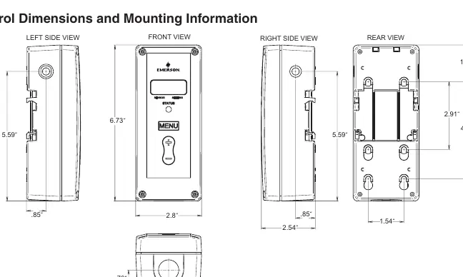
The control should be mounted according to the dimensions provided in the manual. Ensure the environment is suitable for the NEMA 1 enclosure. The unit features a front-facing display and control buttons for easy access to settings.
Wiring
The control supports two main wiring configurations:
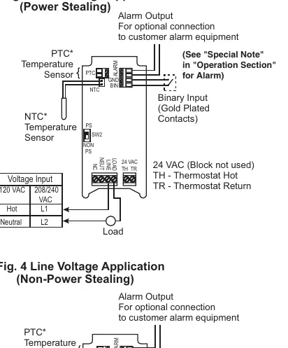
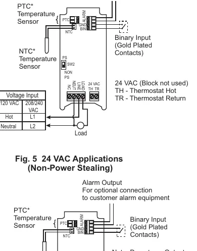
- Power Stealing: Eliminates the need for a neutral wire by drawing power from the load circuit. Check the compatibility chart in the manual to ensure your load is suitable (e.g., load must be greater than 2.5 amps in some cases).
- Non-Power Stealing: Requires a neutral wire connection. This is recommended for systems with defrost timers or devices that interrupt power to the load.
Switch SW2 must be set to 'PS' for Power Stealing or 'Non PS' for Non-Power Stealing applications.
User Menu Settings
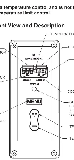
To enter the menu, press and hold the MENU button for 5 seconds. Use the MENU button to advance through items and the plus/minus buttons to change settings. Key settings include:
- CF: Temperature Scale (Fahrenheit or Celsius).
- dFF: Differential (range between Cut In and Cut Out).
- SP: Set Point Mode (Cooling or Heating logic).
- ASd: Anti Short-Cycle Delay (prevents compressor damage).
- LP: Lock Front Panel Keypad.
- OFS: Ambient Temperature Offset (calibration adjustment).
Operation
The control operates based on the selected Set Point (SP) and Differential (dFF). In Cooling mode, the snowflake icon displays; in Heating mode, the flame icon displays. The control can be configured to use the Set Point as either the Cut In or Cut Out temperature.
Troubleshooting
If the display shows 'CaL', the control was not calibrated and should be returned. If the unit does not turn on, verify power, wiring, and that switches SW1 and SW2 are set correctly. For false alarms, ensure the alarm delay (AL) is set long enough to account for defrost cycles or set-back periods.
Practical help
Common problems
Display is blank or off in Power Stealing mode
This is normal if a defrost timer or other device interrupts power. If this is undesirable, wire the control for Non-Power Stealing mode.
False alarms
Ensure the alarm delay (AL) is set long enough to cover temperature variations caused by defrost cycles or set-back periods.
Unit does not turn on
Check that wiring is correct, power is on, and switches SW1 and SW2 are set to the proper positions.
Before use
- Verify system voltage (Line Voltage or 24 VAC).
- Determine if the application requires Power Stealing or Non-Power Stealing wiring.
- Set SW1 (System Mode) to Heat or Cool.
- Set SW2 (Wiring Mode) to PS or Non PS.
- Ensure the correct sensor (NTC or PTC) is connected.
Specs in practice
- Differential (dFF)
- The temperature range between the Cut In and Cut Out points.
- Anti Short-Cycle Delay (ASd)
- Minimum time (in minutes) the load contacts remain open to prevent compressor damage.
- Ambient Temperature Offset (OFS)
- Allows the displayed temperature to be shifted to compensate for mounting or installation factors.
Images and diagrams
- Fig 1: Front panel layout, buttons, and indicators.
- Fig 2: Physical dimensions for mounting.
- Fig 3-5: Wiring diagrams for Power Stealing, Non-Power Stealing, and 24 VAC applications.
Model compatibility
- Compatible with NTC and PTC sensors.
- Not for use as a temperature limit control.
- Do not use for heating water for bathing or washing.

Manual page author
Emily Carter
User documentation editor
Prepares concise manual descriptions and highlights the most useful setup, operation, and maintenance information for readers.