Industrial / Process Sensors
Safety Manual for Emerson Micro Motion 4200 2-Wire Transmitter
Safety manual for the Emerson Micro Motion 4200 2-Wire Transmitter, covering SIS requirements, installation, commissioning, proof testing, and reliability data.
Table of contents
Manual images
Click an image to enlargeImportant Safety Information
This manual provides essential information for installing, commissioning, and proof testing the Micro Motion 4200 2-Wire Transmitter to comply with Safety Instrumented Systems (SIS) requirements. Users must be familiar with standard transmitter and sensor installation, configuration, and maintenance procedures before proceeding.
Installation and Commissioning
To ensure SIS compliance, follow these steps:
- Mounting and Wiring: Use the standard installation manual to mount the transmitter and install sensor wiring.
- Powering: Wire the Channel A passive (external) power to the appropriate output terminal and pins.
- Licensing: Verify that SIL and ChA features are licensed. If not, obtain the license key (LICKEY4200SI) from your local service office and install it via the display, ProLink III, or a field communicator.
- Configuration: Verify all safety parameters, including flow and density calibration parameters (FCF, K1, K2, D1, D2, DT), Lower Range Value (LRV), Upper Range Value (URV), measurement units, HART Primary Variable assignment, low flow cutoff, damping values, and mA Output Fault Action (Upscale or Downscale).
Diagnostics and Configuration
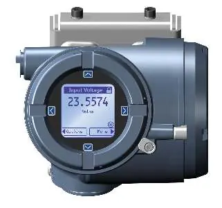
The SIL license enables a mA Output to internal mA Readback comparison diagnostic. If the difference between the programmed mA output and the actual internal readback exceeds 0.2 mA, an Electronics Failed alert becomes active, and outputs will turn off within 5 minutes. The diagnostic is disabled for the first 5 minutes after power-up to allow for wiring verification.
Write Protection: Prevents configuration changes. It is enabled/disabled using the physical dip switch located behind the display module.
Proof Testing
Proof tests are required to detect failures not caught by internal diagnostics. The frequency is determined by your specific reliability calculations.
- Proof Test 1: Includes mA output min-to-max test, checking alarms/configuration, Smart Meter Verification (SMV), verification of onboard temperature measurement, and RAM soft error testing.
- Proof Test 2: Includes a full calibration against a primary standard.
Procedure for Proof Test 1:
- Bypass the safety PLC to avoid false trips.
- Disable write-protection.
- Test mA output using an external device (e.g., fluke meter) for both Upscale and Downscale fault levels.
- Verify sensor temperature against process temperature.
- Power cycle the transmitter and wait 30 seconds.
- Run an SMV test and verify no alarms are present.
- Restore loop operation, enable write-protection, and remove PLC bypass.
Operating Constraints
The 4200 transmitter has a specified safety deviation of 2%. It reports internal failures within 5 minutes and generates a valid signal within 30 seconds of power-on. Always refer to the FMEDA report for detailed failure rates and common cause factors.
Practical help
Common problems
Electronics Failed alert
The difference between programmed mA output and actual readback exceeds 0.2 mA. Check wiring and operation. If the condition persists after 5 minutes, it indicates a component failure.
SIL license not active
Verify license status in the License Manager. If not licensed, obtain the model code LICKEY4200SI from your local service office.
Before use
- Verify transmitter is installed according to the standard installation manual.
- Ensure SIS features (SIL and ChA) are licensed.
- Verify flow and density calibration parameters (FCF, K1, K2, D1, D2, DT).
- Configure Lower Range Value (LRV) and Upper Range Value (URV) for Channel A mA Output.
- Set mA Output Fault Action to Upscale or Downscale.
- Verify HART Primary Variable is assigned to Channel A mA Output.
Images and diagrams
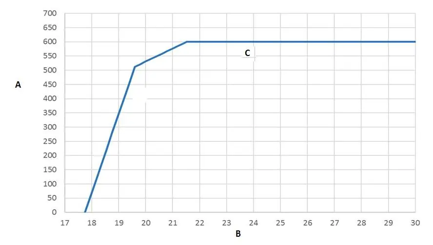
- Wiring diagram for Channel A mA/HART output (externally powered).
- Chart showing the relationship between loop resistance and supply voltage.
Model compatibility
- Requires Micro Motion 4200 2-Wire Transmitter.
- SIS features are enabled through licensing.

Manual page author
Emily Carter
User documentation editor
Prepares concise manual descriptions and highlights the most useful setup, operation, and maintenance information for readers.