Industrial / Process Controllers
Instruction Manual for Varec 2010B/2020B/3500B Series Pressure and Vacuum Relief Valves
Comprehensive instruction manual for Varec 2010B, 2020B, and 3500B series pressure and vacuum relief valves. Includes installation, operation, maintenance, calibration, and replacement parts information.
Quick answers from the manual
Quick answer
- The Varec 2010B/2020B/3500B series are pressure and vacuum relief valves designed to protect storage tanks. Installation requires ensuring the valve is level, the pallet moves freely, and the stem engages the guide. Maintenance involves periodic inspection and cleaning of pallets and seat rings. p. 1, 5, 6
Key actions
- Isolate the valve from tank pressure before servicing. p. 1, 6
- Load pallet weights according to the required setting. p. 5, 7
First start
- Remove shipping materials, check weights, mount the valve on the nozzle using a full-faced gasket, and verify it is level. p. 5
Problems and fixes
Valve not seating
Ensure pallet stem engages stem guide in cover/weatherhood.
p. 5, 6Technical specifications
| Parameter | Value | Meaning | Pages |
|---|---|---|---|
| Pressure Setting Range | 0.3 to 32 osig | Operating pressure range for 2010B/2020B series. | p. 4 |
| Vacuum Setting Range | 0.3 to 32 osig | Operating vacuum range for 2010B/2020B/3500B series. | p. 4 |
Where to find it in the PDF
- Installation p. 5
- Maintenance p. 6
Table of contents
Manual images
Click an image to enlargeQuick guide from the manual
This manual provides instructions for the installation, operation, and maintenance of Varec 2010B, 2020B, and 3500B series pressure and vacuum relief valves. Safety Warning: Always isolate the valve from tank pressure before servicing. Ensure all gas is blocked and pressure is safely vented. Wear appropriate protective equipment if hazardous vapors are present.
Product Overview
These valves are designed to protect low-pressure storage tanks, sludge digesters, and gas holders from excessive pressure and/or vacuum. The 2010B series vents directly to the atmosphere, the 2020B series uses an enclosed outlet adapter, and the 3500B series is a vacuum relief valve.
Installation
Before installation, ensure the valve is compatible with the tank flange. Steps:
- Remove the valve from the shipping container and check for extra loading weights.
- Remove the weatherhood/cover and all packing material from above the pallets.
- Load pressure or vacuum pallet weights as required for the specific setting.
- Weigh the entire pallet assembly to confirm it matches the required setting (Table 5).
- Mount the valve on the flanged nozzle using a full-faced gasket.
- Verify the valve is level to ensure proper pallet operation.
- For Model 2020B, install connecting piping to the outlet flange if required.
Caution: The end of the pallet stem must engage the stem guide in the weatherhood or cover for proper seating. Do not mate a flat face flange to a raised face flange.
Operation
The valves operate automatically. When tank pressure or vacuum approaches the valve setting, the respective pallet lifts off the seat ring to relieve the condition. The pallet automatically re-seats once the pressure or vacuum drops below the setting.
Maintenance
Periodic inspection is required, starting 30 days after commissioning, then every 30 days thereafter. Procedures:
- Inspect pallet inserts for ripples, tears, or nicks.
- Check seating surfaces for debris, abrasion, or pitting.
- Clean all components and replace any showing excess wear.
- For freezing weather, remove pallets or apply silicone grease to pallets, seat rings, and guide posts (not required for All-Weather models).
- Seat ring repair may involve grinding or lapping with a fine compound.
Calibration
To verify the setting, calculate the total necessary weight using Table 5. Check this against the actual weight of the pallet assembly (including loading weights) and adjust as necessary.
Practical help
Common problems
Valve not seating properly
Ensure the pallet stem engages the stem guide in the weatherhood or cover. Check for debris on the seat ring.
Ice accumulation
Use 'All-Weather' models or apply silicone grease to pallets, seat rings, and guide posts (not required for All-Weather models).
Incorrect pressure/vacuum setting
Verify pallet assembly weight using Table 5 and adjust loading weights accordingly.
Before use
- Verify the valve is level.
- Ensure the pallet moves freely within guide posts.
- Check that the pallet rests flat on the seat ring.
- Confirm the valve is isolated from tank pressure before installation.
- Use appropriate full-faced gaskets for mounting.
Specs in practice
- Pressure/Vacuum Setting
- The pressure or vacuum level at which the valve pallet lifts to relieve excess pressure or vacuum.
- Nominal Pipe Size
- The size of the inlet/outlet connection, determining the valve capacity and replacement part compatibility.
- Weight Tolerance
- The allowable deviation (+5%/-5%) for the pallet assembly weight to achieve the required setting.
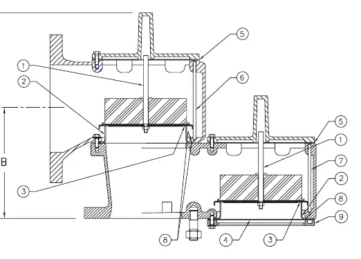
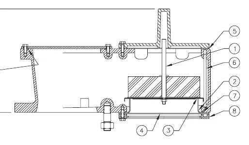
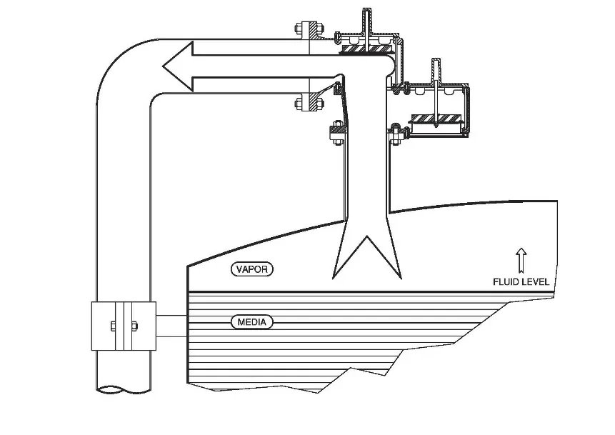
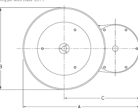
Images and diagrams
- Figure 2 and 3 illustrate the pressure and vacuum control operation, showing how the pallet lifts to vent vapor or allow air intake.
- Figures 4-9 provide dimensional drawings for different models and settings.
Model compatibility
- Do not mate a flat face flange to a raised face flange; use a spacer if necessary.
- Steel and iron valves should be painted on external surfaces immediately after installation.

Manual page author
Michael Turner
Technical manual editor
Reviews PDF manuals for structure, safety notes, and practical product details so readers can find the right information quickly.