Lighting / Stage Lighting
User Manual for Equinox Helix 100W Gobo Flower
Quick guide for the Equinox Helix 100W Gobo Flower. Learn about DMX setup, operating modes, menu settings, power linking, and safety instructions.
Table of contents
Manual images
Click an image to enlargeQuick guide from the manual
The Equinox Helix 100W Gobo Flower is a professional lighting fixture designed for stage and event use. Before initial startup, inspect the unit for transport damage. Ensure the mains supply voltage is between 100-240V AC, 50/60Hz. This unit is for professional use only and must be installed by a qualified technician. Always disconnect the power when not in use or before cleaning.
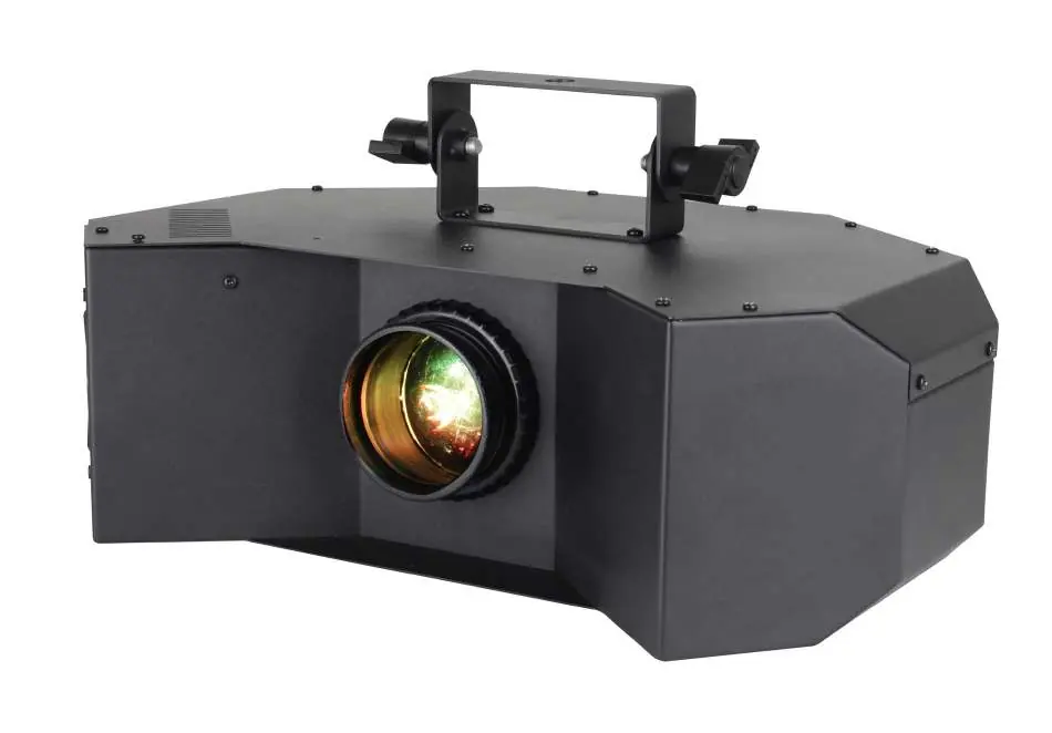
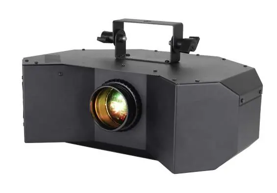
Product overview
The fixture features a 100W cool white LED (7400K) with a 40-degree beam angle. It includes 11 static gobos plus open, and 9 colours plus open. The unit is fan-cooled and supports 0-100% dimming and variable strobe. It is equipped with a 4-push button menu with an LED display, IEC power input/output, and 3-pin XLR input/output for DMX control.
Installation and safety
The fixture must be installed in accordance with local territory regulations. It is a Risk Group 2 LED product; do not view the light output with optical instruments. Never connect this equipment to a dimmer pack. If the unit has been exposed to drastic temperature fluctuations, allow it to reach room temperature before connecting power to avoid condensation damage. The unit contains no user-serviceable parts; all repairs must be carried out by a qualified technician.
Operating instructions
The unit is controlled via a menu system on the rear panel. Use the MENU, UP, DOWN, and ENTER buttons to navigate settings:
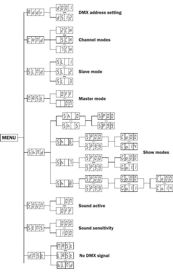
- Addr: Set the DMX address (1-512).
- CHNd: Select DMX channel mode (2, 5, or 7 channels).
- SLNd: Configure Slave mode (SL1, SL2, or SL3).
- NASt: Set Master mode (ON/OFF).
- SHNd: Select Show modes (0-8) and adjust speed (SP00-SP99).
- SOUN: Enable/disable Sound active mode.
- SENS: Adjust sound sensitivity (0-100).
- dNSt: Set behavior when DMX signal is lost (Master/Slave, Hold, or Blackout).
- NANU: Manual mode for testing Dimmer, Strobe, Colour, Gobo, and Rotation.
DMX setup
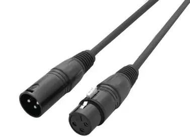
The fixture supports DMX-512 protocol. Each unit requires a start address. When linking multiple fixtures, use the shortest cable path possible. Always use a DMX terminator (120 Ohm resistor) on the last unit in the chain to prevent erratic behavior. The unit requires standard 3-pin or 5-pin XLR connectors for data input/output.
Power linking
The fixture provides power linking via the power output on the rear. You can connect a maximum of 16 fixtures at 240V or 8 fixtures at 120V. Do not exceed these limits. Note that other fixtures connected to the power chain may have different power consumption requirements.
Practical help
Common problems
Unit not responding to DMX
Check the DMX address, ensure the unit is in the correct DMX channel mode, and verify cable integrity.
No power
Check the power cable connection and the fuse (T2A 250V).
Erratic behavior
Ensure the DMX line is terminated with a 120 Ohm resistor at the last fixture.
Condensation inside the unit
If exposed to drastic temperature changes, leave the unit switched off until it reaches room temperature.
Before use
- Inspect the unit for damage caused during transportation.
- Verify mains supply voltage is 100-240V AC, 50/60Hz.
- Ensure the unit is installed by a qualified technician.
- Check that the power cable is not crimped or damaged.
- Confirm the DMX cables are standard 3-pin or 5-pin XLR.
Specs in practice
- DMX Channels
- Selectable 2, 5, or 7 channel modes for control flexibility.
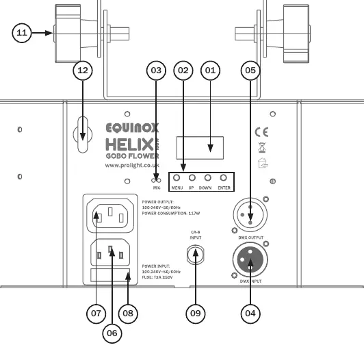
Images and diagrams
- The rear panel diagram identifies the LED display, menu buttons, microphone, DMX input/output, and power input/output.
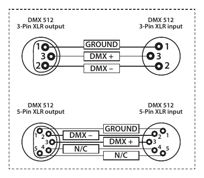
- The DMX wiring diagram shows the pin configuration for 3-pin and 5-pin XLR connectors.
Model compatibility
- Professional use only; not for household use.
- Compatible with CA-8 remote controller (sold separately).

Manual page author
Emily Carter
User documentation editor
Prepares concise manual descriptions and highlights the most useful setup, operation, and maintenance information for readers.