Industrial / Access Control
Installation Guide for Security Brands Ascent X1 Cellular Entry System
Quick installation and wiring guide for the Security Brands Ascent X1 cellular entry system. Includes mounting instructions, power and relay wiring diagrams, and initial setup steps.
Table of contents
Manual images
Click an image to enlargeImportant Information
Safety Warning: Automatic gates can cause serious injury or death. Always ensure the gate path is clear before operating. Reversing or other safety devices should always be used.
Activation: The Ascent unit will not work until the activation process is complete. Refer to the included Activation Guide to activate the unit.
Cellular Connection: This is a cellular accessory. An uninterrupted cellular connection cannot be guaranteed. An emergency egress or primary entry mechanism (such as a transmitter, fire box, or mechanical release) should always be used.
Unpacking and Mounting
Ensure all items are present: Ascent Unit, 12-V AC/DC Adapter (PS-12DC1), Key, 4x Carriage Bolts, 4x Hex Nuts, and Screwdriver.
Mounting Instructions:
- Unlock and open the unit faceplate.
- We recommend mounting the unit on a gooseneck pedestal using the included mounting hardware.
- Use all four carriage bolts when mounting the unit to a pedestal.
- If using alternate mounting, the 4G LTE Antenna Extension Kit (Model 16-ANTX-1) must be purchased and installed to avoid signal loss.
- Seal all openings created in the enclosure to prevent damage.
Wiring Connections
Power Source:
- Verify your power source is compatible: 12-24 VAC/DC (no more than 10% beyond this range).
- Current draw: less than 190 mA @ 12 VDC or less than 160 mA @ 24 VDC.
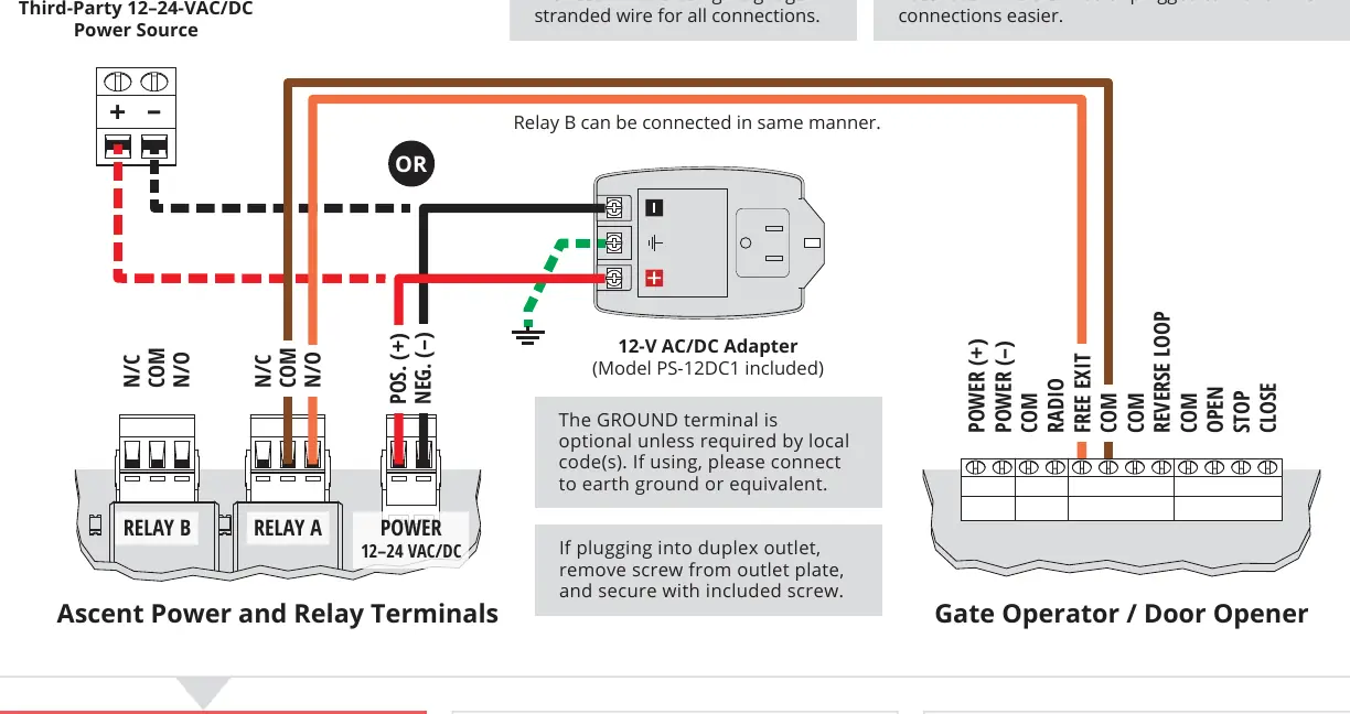
- Connect wires to the Power Terminals. Ensure positive is connected to positive and negative to negative.
- We recommend using 18-gauge stranded wire for all connections.
Relay and Wiegand Connections:
- Relay Terminals: Used for wiring to gate operators or door openers. Consult your gate/door opener manual for exact connections.
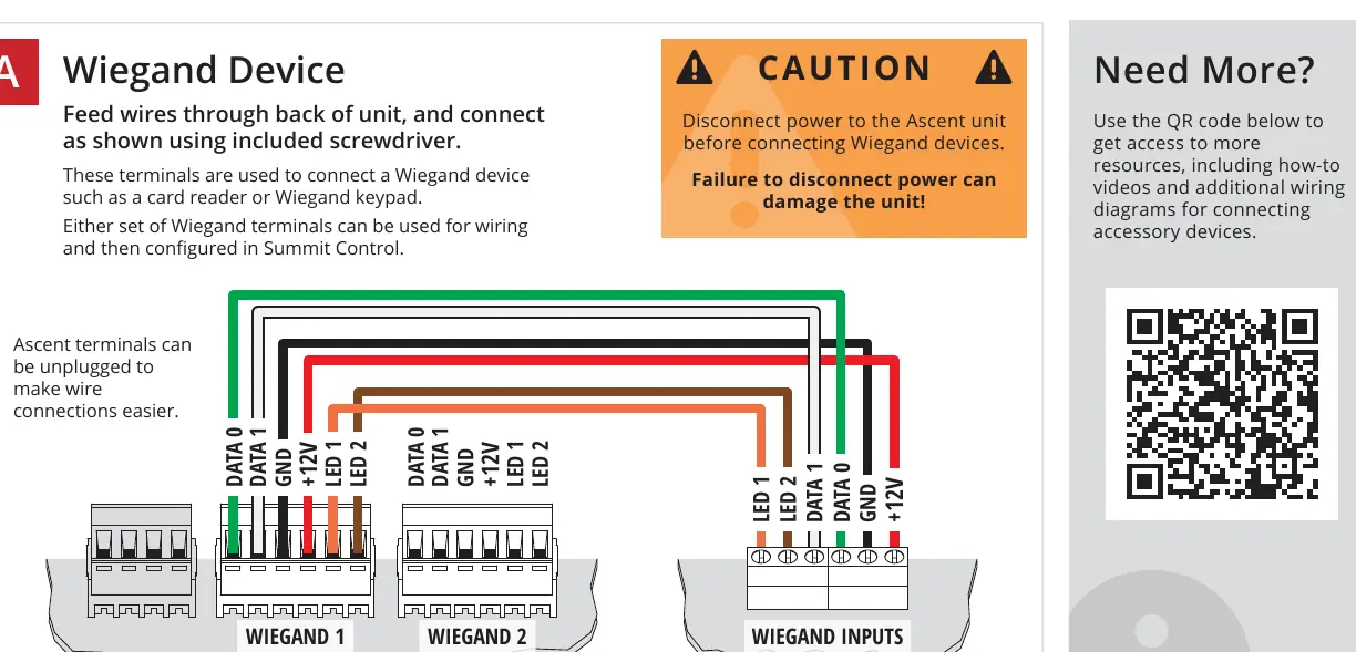
- Wiegand Terminals: Used for connecting Wiegand devices such as card readers or keypads. Disconnect power to the Ascent unit before connecting Wiegand devices.
- Ascent terminals can be unplugged to make wire connections easier.
Setup and Testing
- Before proceeding, double-check all wiring and ensure the unit has power.
- Key in the temporary code 2012 on the keypad to confirm the gate opens.
- If the gate opens, close and secure the unit faceplate.
- Adding and deleting codes is managed through Summit Control, not the keypad.
- Follow the Activation Guide to create an account and begin using the Ascent system.
Manufacturer information
Security Brands, Inc.
Practical help
Common problems
Unit has no signal
If using alternate mounting, ensure the 4G LTE Antenna Extension Kit (Model 16-ANTX-1) is installed.
Unit will not work
Ensure the activation process is complete as per the separate Activation Guide.
Gate does not open during test
Double-check all wiring, ensure the unit has power, and verify relay connections to the gate operator.
Before use
- Verify power source is 12-24 VAC/DC.
- Ensure gate path is clear of obstructions.
- Confirm activation process is complete.
- Use 18-gauge stranded wire for all connections.
- Seal all enclosure openings.
Specs in practice
- Input Voltage
- 12-24 VAC/DC (do not exceed 10% beyond this range).
- Current Draw (12 VDC)
- Less than 190 mA.
- Current Draw (24 VDC)
- Less than 160 mA.
Images and diagrams
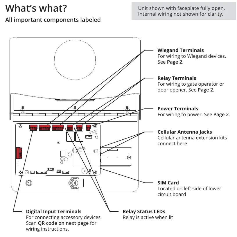
- Power Terminals: Connect to 12-24 VAC/DC power source.
- Relay Terminals: Connect to gate operator or door opener.
- Wiegand Terminals: Connect to card readers or keypads.
- Cellular Antenna Jacks: For connecting antenna extension kits.
Model compatibility
- Compatible with solar applications.
- Requires 4G LTE Antenna Extension Kit (Model 16-ANTX-1) for non-pedestal mounting.

Manual page author
David Miller
Documentation analyst
Organizes user manual content into clear summaries, with attention to model details, product context, and everyday usability.