Industrial / Access Control
Installation Guide for Security Brands Ascent M8 Multi-Tenant Entry System
Comprehensive installation and wiring guide for the Security Brands Ascent M8 entry system. Includes step-by-step mounting instructions, power and relay wiring diagrams, Wiegand device connection, and initial system testing procedures.
Table of contents
Manual images
Click an image to enlargeQuick Start Guide
The Ascent M8 is a cellular accessory for gates and doors. Please note that an uninterrupted cellular connection cannot be guaranteed, so an emergency egress or primary entry mechanism should always be used. The unit will not function until the activation process is complete. For support, contact Summit Control at 972-474-6422 (available Monday-Friday, 8am-5pm Central).
Unpacking and Mounting
Ensure all items are present before beginning: Ascent Unit, 24-V AC/DC Adapter, Key, 4 Carriage Bolts, 4 Hex Nuts, and a Screwdriver.
- Unlock and Open: Unlock the unit to access the interior for mounting and wiring.
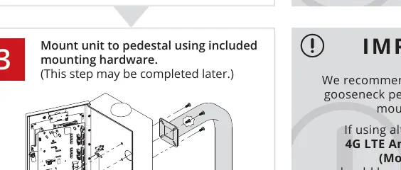
- Mounting: We recommend mounting the unit on a gooseneck pedestal using the included hardware. Use all four carriage bolts.
- Antenna: Leave the "hockey puck" antenna in place even if using an antenna extension. If using alternate mounting, the 4G LTE Antenna Extension Kit (Model 16-ANTX-1) must be purchased and installed to avoid signal loss.
- Sealing: Seal all openings created in the enclosure to prevent damage.
Wiring and Connections
Feed wires through the back of the unit and connect them using the included screwdriver. Terminals can be unplugged to make connections easier.
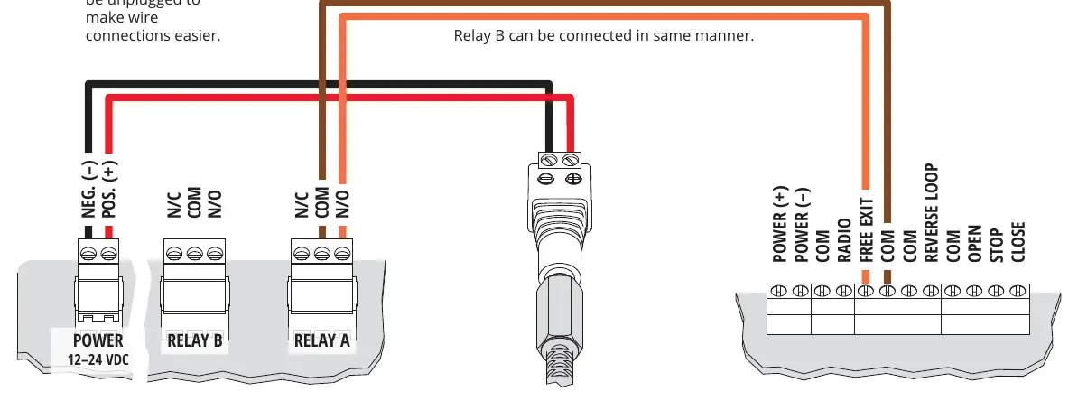
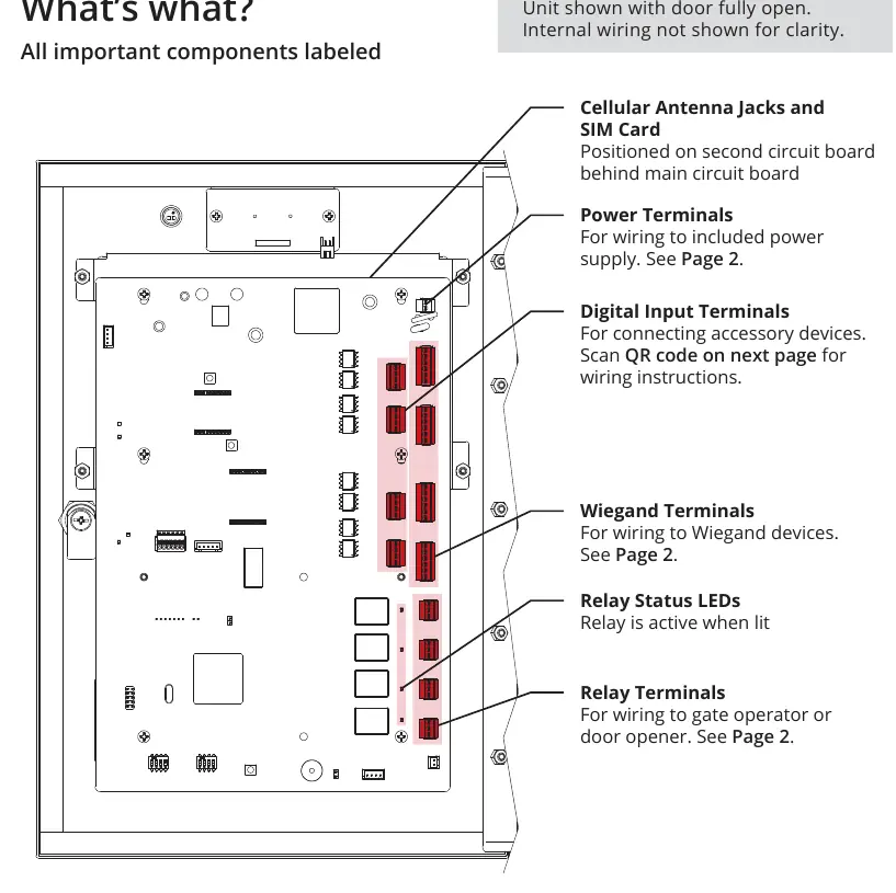
- Power: Connect the 24-V AC/DC adapter to the Power Terminals. Ensure positive is connected to positive and negative to negative. Reversing polarity can damage the unit and void the warranty. We recommend using 18-gauge stranded wire for all connections.
- Relays: Connect gate operator or door opener wires to Relay A or Relay B terminals as required.
Wiegand Device Connection
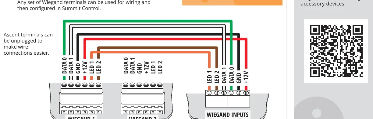
The Ascent M8 supports Wiegand devices such as card readers or keypads.
- Disconnect Power: Always disconnect power to the Ascent unit before connecting Wiegand devices to prevent damage.
- Wiring: Connect the Wiegand device wires to the Wiegand 1 or Wiegand 2 terminals. Any set of Wiegand terminals can be used and then configured via Summit Control.
System Activation and Testing
Before finalizing installation, perform a test:
- Double-check all wiring and ensure the unit has power.
- Key in the temporary code 2012 on the keypad.
- Confirm the gate opens. If it does, close and lock the unit.
- Follow the included Activation Guide to create an account and begin using the Ascent system.
Safety and Warnings
- Automatic gates can cause serious injury or death. Always check that the gate path is clear before operating.
- Reversing or other safety devices should always be used.
- This unit is a cellular accessory; it is not a substitute for primary emergency egress mechanisms.
Manufacturer information
Security Brands, Inc.
Practical help
Common problems
Unit will not work
The activation process must be completed. Refer to the included Activation Guide.
No signal
If using alternate mounting, ensure the 4G LTE Antenna Extension Kit (Model 16-ANTX-1) is installed.
Unit damaged during installation
Ensure correct polarity when connecting power (positive to positive, negative to negative) and disconnect power before wiring Wiegand devices.
Before use
- Verify all components are present (Unit, Adapter, Key, Bolts, Nuts, Screwdriver).
- Ensure the gate path is clear of obstructions.
- Have 18-gauge stranded wire ready for connections.
- Confirm the primary emergency egress mechanism is installed.
- Ensure the unit is mounted on a gooseneck pedestal or equivalent.
Specs in practice
- Wiring Gauge
- 18-gauge stranded wire is recommended for all connections.
Images and diagrams
- Power/Relay Terminals: Shows connection points for power supply and gate operator inputs.
- Wiegand Inputs: Shows wiring for card readers or keypads (Data 0, Data 1, GND, +12V, LED 1, LED 2).
Model compatibility
- Requires activation via Summit Control.
- Not a standalone emergency egress device; must be used with a secondary mechanism.
- Supports Wiegand-compatible card readers and keypads.

Manual page author
Michael Turner
Technical manual editor
Reviews PDF manuals for structure, safety notes, and practical product details so readers can find the right information quickly.