Computers / PC Components
Gigabyte 12QM-AM5I700-11XAR Motherboard Installation Guide
A comprehensive installation guide for the Gigabyte 12QM-AM5I700-11XAR motherboard. This guide covers the step-by-step process for installing the CPU, memory, expansion cards, power supply, storage drives, and connecting internal cables...
Table of contents
Manual images
Click an image to enlargeQuick Installation Guide
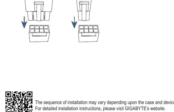
This guide provides the essential steps for installing your Gigabyte motherboard into a computer system. Please note that the installation sequence may vary depending on the specific computer case and components used. Always refer to the individual component manuals for detailed specifications.
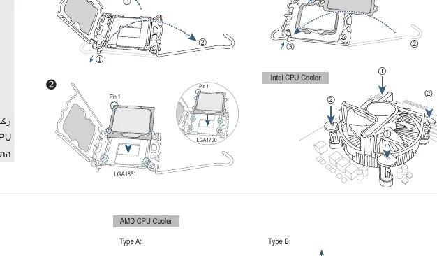
Step 1: Installing CPU and CPU Cooler
Carefully install the CPU into the socket. Ensure the CPU is correctly aligned with the socket pins. Install the CPU cooler according to the manufacturer's instructions, ensuring proper thermal contact with the processor.
Step 2: Installing Memory
Insert the memory modules into the DIMM slots. Ensure the modules are fully seated and the locking tabs are engaged.
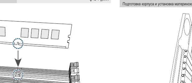
Step 3: Preparing Case and Installing Motherboard
Prepare the computer case by installing the necessary standoffs. Place the motherboard into the case and secure it with screws, ensuring it aligns correctly with the I/O shield.
Step 4: Installing Expansion Cards
Insert expansion cards (such as graphics cards) into the appropriate PCIe slots on the motherboard. Secure the card bracket to the case.
Step 5: Installing Power Supply
Install the power supply unit (PSU) into the designated area of the case and secure it with screws.
Step 6: Installing Storage Drives
Install hard drives (HDD) and optical drives into the drive bays. Connect the necessary data (SATA) and power cables to the drives.
Step 7: Connecting Internal Cables
Connect the necessary cables from the power supply and case front panel to the motherboard's internal headers. This includes the 24-pin ATX power, CPU power, and front panel connectors (HDD LED, Reset Switch, etc.).
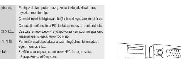
Step 8: Connecting Peripherals
Connect external peripherals such as a keyboard, mouse, and monitor to the rear I/O ports of the motherboard.
Manufacturer information
Gigabyte Technology Co., Ltd.
Practical help
Common problems
Installation sequence varies
The order of installation may change depending on the specific computer case and devices used. Always adapt the steps to your hardware configuration.
Before use
- Ensure the computer case is prepared with correct standoffs.
- Verify CPU compatibility with the AM5 socket.
- Ensure all necessary cables (power, data) are available.
- Check that all components (CPU, RAM, PSU) are compatible with the motherboard.
Images and diagrams
- CPU installation diagram highlights alignment for LGA1700 and LGA1851 sockets.
- Internal connectors diagram illustrates the connection points for HDD LED and Reset Switch headers.
- Storage installation diagram shows the connection points for M.2 and SATA drives.
Model compatibility
- Supports AMD AM5 socket processors.

Manual page author
Emily Carter
User documentation editor
Prepares concise manual descriptions and highlights the most useful setup, operation, and maintenance information for readers.