Computers / PC Components
Gigabyte PC Component Installation Guide 12QM-MBQUICK-103XR
A comprehensive, multilingual installation guide for Gigabyte PC components, covering the assembly of CPUs, memory, motherboards, power supplies, and internal peripherals.
Table of contents
Manual images
Click an image to enlargeQuick Guide from the Manual
This document provides a general overview of the PC assembly process. Please note that the sequence of installation may vary depending on the specific computer case and hardware devices used. For detailed, component-specific installation instructions, always refer to the official GIGABYTE website.
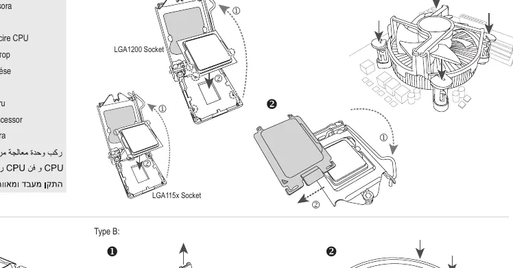
CPU and CPU Cooler Installation
Step 1: Install the CPU and the CPU cooler onto the motherboard. Ensure you follow the specific mounting instructions for your CPU socket type (Intel LGA115x/LGA1200 or AMD). Align the cooler correctly with the socket to ensure proper thermal contact.
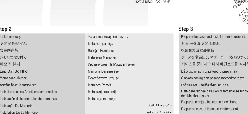
Memory Installation
Step 2: Insert the memory modules into the DIMM slots on the motherboard. Ensure the modules are fully seated and the locking tabs click into place.
Case Preparation and Motherboard Installation
Step 3: Prepare the computer case by installing the necessary standoffs. Place the motherboard into the case and secure it using the appropriate screws.
Expansion Card Installation
Step 4: Install any required expansion cards (such as graphics cards) into the PCIe slots on the motherboard. Secure the card bracket to the case chassis.
Power Supply Installation
Step 5: Mount the power supply unit (PSU) into the designated area of the computer case and secure it with screws.
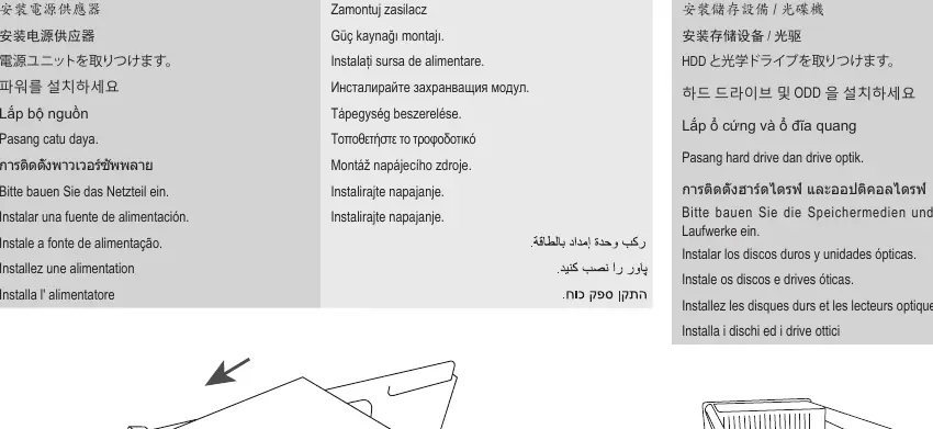
Storage Drive Installation
Step 6: Install hard drives (HDD) and optical drives into the drive bays of the case. Secure them according to the case design.
Internal Cable Connections
Step 7: Connect all necessary internal cables to the motherboard connectors. This includes the 24-pin ATX power, CPU power, front panel connectors (HDD LED, Reset Switch, Power Switch), and any other required headers.

Peripheral Connection
Step 8: Connect external peripherals such as the keyboard, mouse, and monitor to the rear I/O ports of the motherboard.
Manufacturer information
Gigabyte Technology Co., Ltd.
Practical help
Common problems
Installation sequence varies
The order of installation depends on your specific case and hardware; adjust the steps as necessary for your build.
CPU cooler mounting
Ensure you identify the correct socket type (Intel vs. AMD) before attempting to mount the cooler.
Before use
- Prepare the computer case by installing standoffs.
- Verify CPU and motherboard socket compatibility.
- Ensure all necessary cables are available for internal connections.
- Check that the power supply fits the case mounting points.
Images and diagrams
- Step 1 illustrates the difference between Intel and AMD CPU cooler mounting.
- Step 7 provides a visual guide for connecting front panel headers like HDD LED and Reset Switch.
Model compatibility
- Installation steps are general and may vary based on specific hardware components and case design.

Manual page author
Michael Turner
Technical manual editor
Reviews PDF manuals for structure, safety notes, and practical product details so readers can find the right information quickly.