Computers / PC Components
Gigabyte Motherboard Installation Guide 12QM-MBQUICK-13XAR
A comprehensive installation guide for Gigabyte motherboards, covering the step-by-step process of installing the CPU, memory, expansion cards, power supply, storage drives, and connecting internal and external peripherals.
Table of contents
Manual images
Click an image to enlargeQuick Installation Guide
This guide provides a general overview of the installation process for Gigabyte motherboards. Please note that the specific sequence of installation may vary depending on the computer case and devices used. Always refer to the specific manuals for your case and components for detailed instructions.
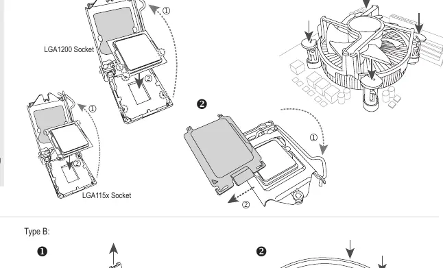
Step 1: CPU and CPU Cooler
Install the CPU into the socket and attach the CPU cooler. Ensure you are using the correct mounting method for your socket type (LGA115x, LGA1200, or AMD). Follow the cooler manufacturer's instructions for applying thermal paste and securing the fan.
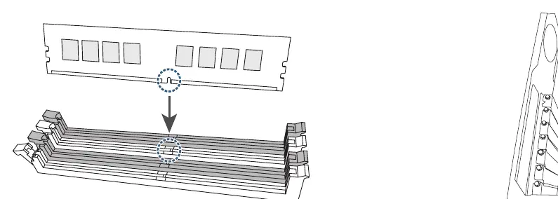
Step 2: Memory Installation
Insert the memory modules into the DIMM slots. Ensure the notches on the memory module align with the slot key. Press down firmly until the clips lock the module into place.
Step 3: Case Preparation and Motherboard Installation
Prepare the computer case by installing the I/O shield (if not pre-installed) and standoffs. Carefully place the motherboard into the case and secure it with screws.
Step 4: Expansion Cards
Install any expansion cards (such as graphics cards) into the PCIe slots. Secure the card bracket to the case chassis.
Step 5: Power Supply
Install the power supply unit (PSU) into the case. Ensure it is securely fastened and positioned to allow for proper cable management.
Step 6: Storage Drives
Install hard drives (HDD) and optical drives into the drive bays. Secure them with screws or tool-less mechanisms provided by the case.
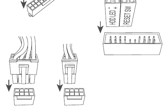
Step 7: Internal Connections
Connect the necessary cables to the motherboard. This includes the 24-pin ATX power, CPU power, front panel connectors (power switch, reset, LEDs), SATA cables for storage, and M.2 drives if applicable.
Step 8: Peripheral Connection
Connect external peripherals such as the keyboard, mouse, and monitor to the rear I/O panel of the motherboard.
Manufacturer information
Gigabyte Technology Co., Ltd.
Practical help
Common problems
Installation sequence varies
The order of installation may change depending on your specific case and components. Always check your case manual if the provided steps do not align with your hardware.
CPU cooler compatibility
Ensure the cooler is compatible with your specific CPU socket type (LGA115x, LGA1200, or AMD) before attempting installation.
Before use
- Prepare the computer case (install standoffs and I/O shield).
- Verify CPU and CPU cooler compatibility with the motherboard socket.
- Ensure memory modules are compatible with the motherboard slots.
- Have a compatible power supply unit (PSU) ready.
- Gather necessary tools, such as a screwdriver.
Specs in practice
- LGA115x/LGA1200
- Intel CPU socket types requiring specific cooler mounting brackets.
Images and diagrams
- Step 1 illustrates the orientation and mounting for Intel and AMD CPU sockets.
- Step 7 shows the connection points for internal cables, including SATA and M.2 slots.
Model compatibility
- Installation sequence may vary depending on the specific case and devices used.

Manual page author
David Miller
Documentation analyst
Organizes user manual content into clear summaries, with attention to model details, product context, and everyday usability.