Computers / PC Components
Installation Guide for Gigabyte 12QM-MBQUICK-200XR
Quick installation guide for the Gigabyte 12QM-MBQUICK-200XR motherboard. Covers step-by-step instructions for installing the CPU, RAM, motherboard, expansion cards, power supply, storage, and connecting internal cables and peripherals.
Table of contents
Manual images
Click an image to enlargeQuick guide from the manual
This document provides a general installation sequence for Gigabyte motherboards. Please note that the specific installation steps may vary depending on the PC case and components used. Always consult the detailed manual provided with your specific motherboard model for precise compatibility, pinout diagrams, and safety instructions.
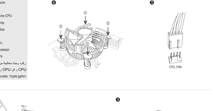
CPU and CPU Cooler Installation
Ensure the CPU socket matches your processor type (e.g., LGA1700). Carefully align the CPU with the socket, ensuring Pin 1 is correctly oriented. Apply thermal paste if required by your cooler, then secure the CPU cooler over the processor according to the manufacturer's instructions.
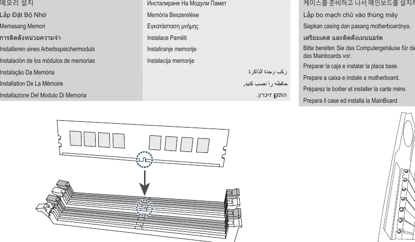
Memory Installation
Identify the memory slots on the motherboard. Open the locking clips on the slots. Align the memory module with the slot, ensuring the notch on the module matches the key in the slot. Press down firmly until the module clicks into place and the clips lock automatically.
Motherboard Installation
Prepare the computer case by installing the necessary standoffs. Place the motherboard into the case, aligning it with the standoffs and the rear I/O shield. Secure the motherboard using the appropriate screws.
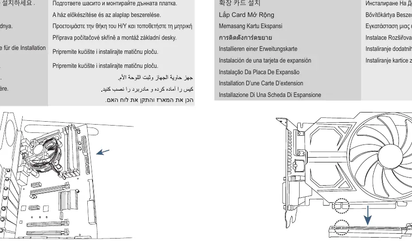
Expansion Card Installation
Locate the appropriate expansion slot (e.g., PCIe). Remove the corresponding slot cover from the back of the case. Insert the expansion card into the slot until it is fully seated and secure it to the case bracket with a screw.
Power Supply Installation
Install the power supply unit (PSU) into the designated area of the case. Secure it with screws. Ensure the PSU is oriented to allow for proper airflow.
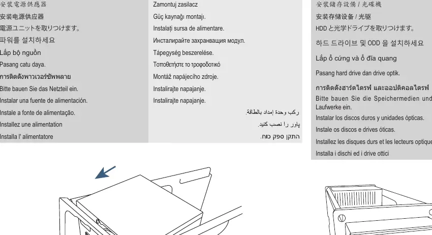
Storage Installation
Install hard drives (HDD) or optical drives into the drive bays. Secure them with screws or tool-less mechanisms. Connect the necessary data cables (e.g., SATA) and power cables from the PSU.
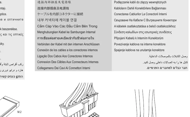
Internal Connections
Connect the necessary cables to the internal motherboard headers. This includes the 24-pin ATX power connector, CPU power connector, front panel headers (power switch, reset switch, LEDs), USB headers, and audio headers. Ensure all connections are fully seated.
Peripheral Connections
Connect external peripherals such as the keyboard, mouse, and monitor to the rear I/O panel of the motherboard. Ensure all connections are secure before powering on the system.
Manufacturer information
Gigabyte Technology Co., Ltd.
Practical help
Common problems
System fails to boot
Check that the CPU is seated correctly, RAM modules are fully inserted, and all power cables (24-pin and CPU power) are securely connected.
No display output
Ensure the monitor is connected to the graphics card (if installed) or the motherboard video output, and that the expansion card is fully seated in its slot.
Before use
- Verify that the CPU socket type matches your processor.
- Ensure the case standoffs are installed before mounting the motherboard.
- Check that all RAM modules are fully inserted into the slots.
- Confirm all power cables are connected to the motherboard and components.
- Ensure the I/O shield is installed in the case before mounting the motherboard.
Images and diagrams
- Step 1 illustrates the CPU and cooler installation, highlighting the Pin 1 alignment.
- Step 7 shows the connection of internal cables, including SATA and front panel headers.
Model compatibility
- The installation sequence may vary depending on the specific PC case and devices used.

Manual page author
Emily Carter
User documentation editor
Prepares concise manual descriptions and highlights the most useful setup, operation, and maintenance information for readers.